SkyTrac Systems Ltd.
Document Revision 01.000 DOC0595 Page 4 of 21
Restricted Proprietary and Confidential Information
1 B
ATTERY
R
EPLACEMENT
P
ROCEDURES
The battery replacement procedure is given as a number of steps below. The actual
appearance of parts may differ from those shown. Pictures are for reference only.
2 DSAT-300E
Note: To avoid damage to the unit due to Electro Static Discharge (ESD) the battery
replacement should be performed in an ESD controlled environment, i.e. on an electrically
conductive mat with the person performing the replacement using an ESD strap connected
to the mat/ground at all times. Avoid touching the circuit board and its’ components.
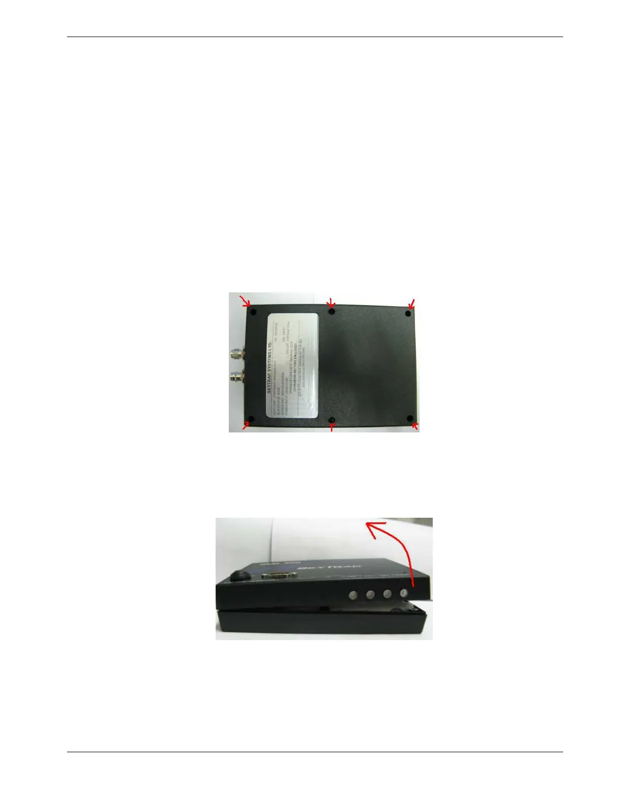
1. Unfasten and remove the screws from the DSAT-300 at 6 locations using a #1
Phillips head screw driver (screw: Phillips #4-40). Retain the screws for later use.
Figure 1 – Screw Locations
2. Turn the DSAT-300 over and lift the top enclosure from the right side as shown in
Figure 2
, creating a hinge on the left end of the enclosure.
Figure 2 – Unhinging the Enclosures

 Loading...