Do you have a question about the Skyworth SMVH24A-5C1A3NG and is the answer not in the manual?
Lists error codes, their causes, and troubleshooting solutions.
Provides step-by-step guides for safely removing indoor and outdoor units.
Lists the different air conditioner models covered in the manual.
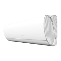
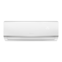
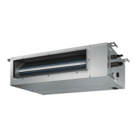
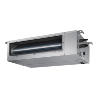
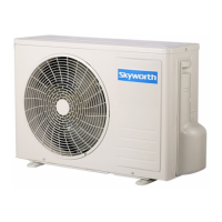
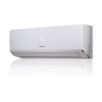
Shows images of indoor/outdoor units and the remote controller.
Highlights important warnings regarding handling, installation, and operation.
Lists critical warnings related to the use and handling of the appliance and its refrigerant.
Details the technical parameters of the indoor and outdoor units.
Presents graphical data on cooling and heating performance based on compressor speed.
Shows how cooling and heating capacity changes with ambient temperature.
Provides notes for understanding the data sheet.
Displays noise level graphs for indoor and outdoor units.
Details how to operate the air conditioner using the remote controller.
Explains MODE and FAN button functions for operation modes and fan speed.
Describes how to control the up/down and left/right swing functions of the louvers.
Details temperature adjustment, TURBO, HEALTH, SLEEP, I FEEL, CLEAN, and CLOCK functions.
Explains TIMER, QUIET, ECO, LIGHT, SMART, Child Lock, and Temp Display functions.
Covers Timing Defrost, Temperature Modes, Manual Defrost, Freon Collection, Memory, and Battery Replacement.
Instructions on how to download the mobile application.
Overview of the smart module and its capabilities.
Lists the technical parameters of the smart module.
Important precautions for using the smart APP and Wi-Fi connection.
Steps for adding the air conditioner to the smart APP.
Steps for the APP to find, connect, and configure the air conditioner.
Provides important notices regarding hotspot name and password.
Instructions for connecting the air conditioner to the Wi-Fi network via the APP.
Steps for registering and configuring the air conditioner for iOS users.
Describes network switching, credential entry, and interface navigation.
Provides a notice regarding the network name used in the guide.
How to search for the AC on WLAN and general operational notices for the APP.
Describes the main control interface of the APP, including buttons and icons.
Details the options available in the APP menu: add, modify, delete AC, settings, and version.
Lists requirements, troubleshooting steps, and diagrams for APP and Wi-Fi issues.
Illustrates communication paths between devices via wireless router or cloud server.
Troubleshooting for persistent failures, offline status, APP crashes, disconnections, and feedback.
Explains the different states of the Wi-Fi indicator light.
Specifies the module's applicability.
Information on how to provide feedback.
Explains the detailed operation of each control and function.
Lists functions integrated into the mainboard.
Lists the controllable components and functions.
Describes basic control functions for Cooling, Fan, and Heating modes.
Explains the operation of the auto mode.
Describes protection mechanisms and error conditions like sensor and motor malfunctions.
Details additional functions such as Auto, Filter Cleaning, Health, Dry, Energy Saving, and Low Temp Heating.
Describes outdoor power status and behavior during operation and standby.
Describes the 1W standby mode.
Explains the unit's display indicators during power on, running, and sleep modes.
Provides detailed instructions for installing the air conditioner.
Safety guidelines for handling flammable refrigerant during installation.
Specifies qualification requirements for installation and maintenance personnel.
General notes and restrictions for installation.
Notes related to maintenance and ventilation.
Procedure for welding refrigerant system pipes.
Steps for filling the refrigerant correctly.
Safety guidelines for transporting and storing the unit.
Precautions to take before starting installation.
Critical warnings for installation procedures.
Important notices and cautions for installation.
Cautions for installation by authorized personnel.
Guidelines for selecting an appropriate installation site.
Specific instructions for installing the indoor unit.
Specific instructions for installing the outdoor unit.
Safety measures for electrical connections and appliances.
Requirements for proper earthing of the unit.
Guidance on selecting the best location for the indoor unit.
Instructions for mounting the frame on the wall.
Steps for drilling and preparing the piping hole.
Instructions for routing the outlet pipe.
Procedure for connecting the refrigerant pipes to the indoor unit.
Instructions for installing the drain hose.
Steps for connecting electrical wires to the indoor unit.
Instructions for bundling pipes, cords, and hoses.
Procedure for hanging the indoor unit onto the wall mount.
Instructions for fixing the outdoor unit support.
Procedure for installing the drain joint for cooling/heating units.
Steps for securing the outdoor unit to its support.
Procedure for connecting refrigerant pipes between units.
Steps for connecting electrical and control wires between units.
Instructions for neatly routing and securing the pipes.
Procedure for vacuum pumping the refrigerant system.
Methods for detecting refrigerant leaks.
Checklist for verifying proper installation.
Procedure for testing the air conditioner after installation.
Steps to prepare for the test operation.
How to perform the test operation and check functions.
Instructions for adding refrigerant oil and charge when extending pipes.
Instructions for cutting the refrigerant pipe.
Steps to remove burrs from cut pipes.
Instructions for applying insulating pipe.
Steps for fitting the union nut.
Procedure for expanding the pipe port.
How to inspect the expanded port quality.
Shows construction diagrams and dimensions for indoor units.
Construction diagram for the 18K model.
Construction diagram for the 24K model.
Construction diagram for the SMVH24B-5A2A3NG(O) model.
Exploded view and parts list for the indoor unit.
Product codes for indoor unit parts.
Exploded view for the SMVH18A-4C1A3NG(I) indoor unit.
Product codes for indoor unit parts.
Exploded view for the SMVH24A-5C1A3NG(I) indoor unit.
Product codes for indoor unit parts.
Product codes for outdoor unit parts.
Product codes for outdoor unit parts.
Product codes for outdoor unit parts.
Exploded view for the SMVH24B-5A2A3NG(O) outdoor unit.
Product codes for outdoor unit parts.
Wiring diagram for the indoor unit.
Wiring diagrams for outdoor units.
Top view of the indoor unit PCB.
Top view of the outdoor unit PCB.
Bottom view of the indoor unit PCB.
Top view of the outdoor unit PCB.
Bottom view of the outdoor unit PCB.
Lists error codes, their causes, and troubleshooting solutions.
Details troubleshooting for various protection-related error codes.
Details troubleshooting for communication and sensor-related error codes.
Troubleshooting flowchart for system errors and motor issues.
Troubleshooting flowchart for overload and heat dissipation issues.
Troubleshooting flowchart for electronic expansion valve and overload protector issues.
Troubleshooting flowchart for system pressure and voltage issues.
Troubleshooting flowchart for compressor issues.
Troubleshooting flowcharts for various protection and connection issues.
Troubleshooting flowchart for jumper cap and mainboard issues.
Troubleshooting flowchart for IDU fan motor issues.
Troubleshooting flowchart for unit communication issues.
Troubleshooting flowchart for outdoor unit communication circuit.
Troubleshooting flowchart for power supply voltage and fan motor issues.
Troubleshooting flowchart for PFC fault.
Steps to troubleshoot why the AC won't start.
Troubleshooting steps for reduced cooling or heating performance.
Lists potential causes for poor cooling/heating.
Methods to identify the cause of poor cooling/heating.
Solutions for poor cooling/heating performance.
Troubleshooting steps if the horizontal louver does not move.
Steps to troubleshoot if the outdoor fan motor does not operate.
Troubleshooting steps for when the compressor fails to operate.
Troubleshooting steps for refrigerant leaks.
Addresses abnormal sounds and vibrations from the unit.
Table showing resistance values for temperature sensors at various temperatures.
Table showing resistance values for temperature sensors at various temperatures.
Table showing resistance values for temperature sensors at various temperatures.
Step-by-step guide to disassemble the indoor unit.
Steps to remove the panel, display board, and guide louver.
Steps to remove the electric box cover, air filter, and front case.
Steps to remove the electric box, evaporator, and motor press plate.
Instructions for removing the motor and cross flow blade.
Preparations before disassembling the outdoor unit.
Steps to remove the top cover.
Instructions for removing the protective grille.
Steps to remove the grille, panel, axial flow blade, and big handle.
Instructions for removing side plates and the electric box assembly.
Steps to remove the reactor, motor, support, and acoustic cotton.
Instructions for removing the 4-way valve assembly and isolation sheet.
Steps to remove the expansion valve assembly and the compressor.
| Refrigerant | R410A |
|---|---|
| Compressor Type | Rotary |
| Type | Split Type |
| Power Supply | 220-240V, 50Hz |
| Outdoor Unit Noise Level | 52 dB |
| Operating Temperature Range (Cooling) | 18°C to 43°C |