Page 7
5086-2-2018
Serial number
System Unit/Servo Pump installation
- Locate a suitable position to install the System Unit and Servo Pump Unit. Make sure that the selected
mounting position is adequate to support the system unit (approx 25 kg) and servo pump (approx. 10 kg)
- Mount the system unit and servo pump.
- Clean and ush all hoses. Use plastic caps or tape to seal the hose ends before the hoses are installed.
- When routing the hoses, avoid restrictions, hot spots, sharp edges and tight bends (Rmin = 130 mm
for 3/8” hose and 180 mm for ½” hose). Secure hoses with appropriate fastening devices to avoid
chang.
Hose installation
- Connect the servo pump hydraulic inlet/suction hose to hydraulic port S on the system unit. Connect
servo pump hydraulic outlet/pressure hose to hydraulic port P (lter) on system unit. Please refer to
drawing on page 8 for hydraulic port layout on the system unit.
- The Hoses can be connected either vertically or horizontally into the helm pump
(see helm pump description)
- Connect the hoses to the helm pump and the cylinder according to drawing on page 8 and 12.
- Connect the cooling water inlet/outlet hoses to the engine cooling system. Ensure that the hoses are
installed in accordance with this manuals paragraph “Hose Installation”.
Hose connecting
- Connect the temperature sensor leads to the system unit (external contacts). Connect the power leads
from (B-,P-) to Servo Pump (-), and (P+) on system unit external relay to (+) on Servo Pump.
- Connect battery power (24V DC) to the System Unit power terminals (positive cable to (B+) terminal
and negative to (B-) terminal & torque load to 17Nm)
- A 50Amp fuse must be installed in proximity of the batteries on the positive cable run, to protect the
system from damage from possible short circuiting.
For schematic drawings , see page 15 (Twin helm) & page 16 (Single helm).
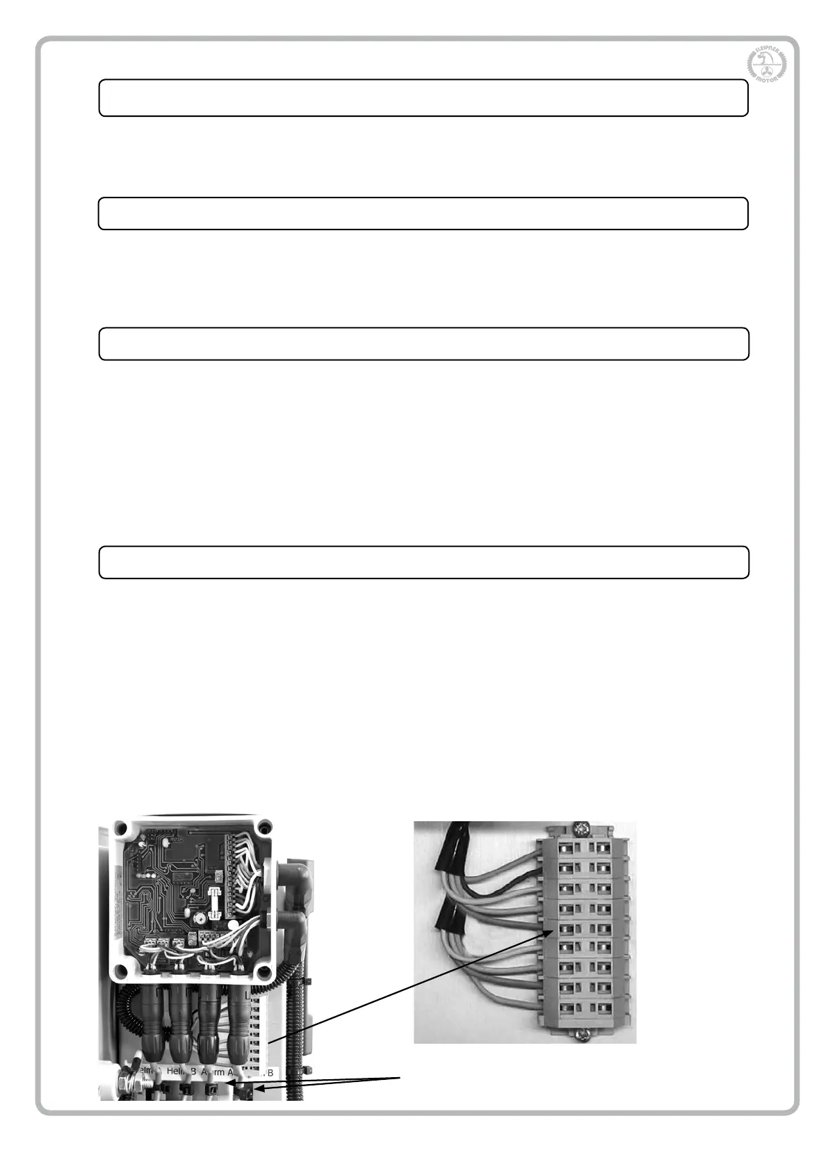
- Connect the “Motor On” and Pilot Signal electrical looms to the external terminal block mounted on the
System Unit.
Power supply and signal leads connecting
Secure cables properly to attachment
points with cable ties
Pilot STB
Pilot GND
Pilot PRT
Joystick STB
Joystick GND
Joystick PRT
Engine 2
Engine GND
Engine 1
ECU external connector layout