Do you have a question about the SLS Audio LS6500 LINE ARRAY and is the answer not in the manual?
Overview of the guide for flying and shaping line arrays, providing hints for array construction.
User assumes responsibility for rigging use, compliance with laws, and component inspection. SLS disclaims liability for misuse.
Defective components require SLS approved parts. Contact factory for replacements to ensure system integrity.
Select the top LS6500 element, remove rear billet arms, and secure cotter pins and billet arms as spares.
Assemble the RLA/3-BB rigging frame. Attach the frame to the LS6500 without rear billets using positive locking pins.
Attach the Rigging Frame to house rigging. Raise the array to a working height and set inter-element splay angles.
Raise the array, add second group of elements, align front billets, and attach pins for rear splay angles.
Raise rigging frame, adjust splay angles for subsequent blocks, and continue until the array is complete.
The rigging for the LS6500 system must not exceed 24 LS6500 boxes per Rigging Frame.
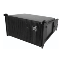
Technical data including operating range, sensitivity, coverage, power handling, SPL, impedance, transducers, dimensions, and finish options.
Clarifications on measurement methods for LF/HF response, sensitivity, coverage angle, power handling, and SPL calculations.
| operating range | 85Hz - 20, 000Hz |
|---|---|
| sensitivity low frequency | 91dB |
| sensitivity high frequency | 101dB |
| horizontal coverage angle | 110 Degrees |
|---|
| power handling 100W | 28 Volts AES/2 |
|---|---|
| power handling 145W | 32 Volts IEC Short Term |
| power handling 46W | 18 Volts IEC Long Term |
| power handling 35W | 15.6 Volts AES/2 |
| recommended amp power low frequency | 200 Watts @ 8 ohms |
| recommended amp power high frequency | 150 Watts @ 8 ohms |
| max SPL low frequency | 111dB Cont. / 117dB Peak |
|---|---|
| max SPL high frequency | 118dB Cont. / 123dB Peak |
| nominal impedance low frequency | 8 Ohms |
|---|---|
| nominal impedance high frequency | 7 Ohms |
| transducer low frequency | 6.5” Bass/Midrange |
| transducer high frequency | PRD500 Ribbon |
| height front side | 7.25” (18.4cm) |
|---|---|
| height rear side | 5.5” (14cm) |
| width | 14” (35.6cm) |
| depth | 10” (25.4cm) |
| weight | 20lbs (9kg) |
| shipping weight | 26lbs (11.8kg) |