Support:
www.slxtechnology.com/support
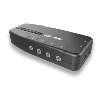
4 Way Signal Booster
with IR Bypass
27820BMR
User Guide
Congratulations on the purchase of your new
SLx Booster. SLx is renowned for producing
high quality electrical accessories and
signal distribution products. Slx Boosters
have a number of features that assist quality
distribution of your TV and/or Radio signals
around your home, including:
• More efcient Switch-Mode Power Supply -
these run cooler saving energy whilst also
making them safer in your home
• Improved gain atness delivering a better
balance across the performance range
• Lower noise gure for optimimum picture
and sound quality
• Greater signal handling capacity to cope
with more channels
• Coaxial connectors – simple to plug in to
standard aerial connections
We are sure you will enjoy using your SLx
Booster, it’s easy to install and incorporates
the latest technology for energy efcient,
long-term, continuous use.
If you have any queries please get in touch
with our technical department at
www.slxtechnology.com/support
Additional Features
Dual Inputs – With separate inputs for UHF TV
and VHF (FM and or DAB) Radio and a built-
in signal combiner your signal distribution
system can easily be expanded to include
high quality radio signals in every room.
SLx Bypass boosters have an IR bypass circuit
and are DigiLink compatible, which means
you have the option to control a digital
satellite receiver via a Link-eye in another
room using the original or a compatible
remote control.
SLx Bypass boosters provide 9V DC on every
outlet to power a Link-eye but also have short-
circuit protection to prevent overload. If the
booster detects a short-circuit it will only shut
down the power on the outlet with the short,
all other outlets will continue to function as
normal.
Please Note: To view output from the
satellite RF2 output you will need a TV
with an analogue tuner.
All SLx boosters comply with RED (The Radio
Equipment Directive 2014/53/EU).
Introduction
2
Inputs DigiLink