(Figure1)
h. EMS: Emissivity setup--press 5 keys for emissivity
settings, press 4 key to save setup and back to
normal status.
(7) LCD
(8) Battery door clip
(9) Battery door: When replace battery door, please
press battery door clip and pull the battery door.
(10) Clesius / Fahrenheit switch: Please open battery
and push the slide switch for con-vertsion
Maintenance
1) Lens cleaning: Blow off lose particles using
clean compressed air. Gently brush remaining
debris away with a moist cotton cloth.
2) Case cleaning: Clean the case with a damp
sponge/cloth and mild soap.
Note:
1) Do not use solvent to clean lens.
2) Do not submerge the unit in water.
(3)—(6) key functions: press 3 key, LCD subdis-
play blinks MAX-MIN-DIF-AVG-HAL-LAL-
STO segment(only main display means normal
measuring mode) press 4 key to enter.
a. MAX: measuring maximum temperature
b. MIN: measuring minimum temperature
c. DIF: Basic on the reading before press 4 key,
compute the difference of current reading.
d. AVG: measuring average temperature
e. HAL: high temperature alarm--when selected
HAL, press 5 keys to set high temperature alarm
trigger and confirmed by pressing 4 key. When
reading over trigger, LCD display HI icon with
BiBi audio sounds.
f. LAL: low temperature alarm--when selected
LAL, press 5 keys to set low temperature alarm
trigger and confirmed by pressing 4 key. When
reading over trigger, LCD display LOW icon with
BiBi audio sounds
g. STO: data storage--when selected STO, lock &
DATA & 1---indicator will shown when press 4 key.
After temperature read out press 6 key to store,
then 2---memory unit will be shown. There 12
groups memory unit available. To recall the stored
data in normal measuring mode by press-ing 6 key,
remove all data by pressing 6 keys for 2 secretary.
A
B
C
D
E
F
G
C
F
HO LD
SC AN
LOW H IGH
DATA
H
J
I
K
(Figure4)
2
SET
STO /CAL
LASER
BACKL IT
MOD E
1
7
5
6
5
8
4
3
(Figure3)
9
Quick start instruction
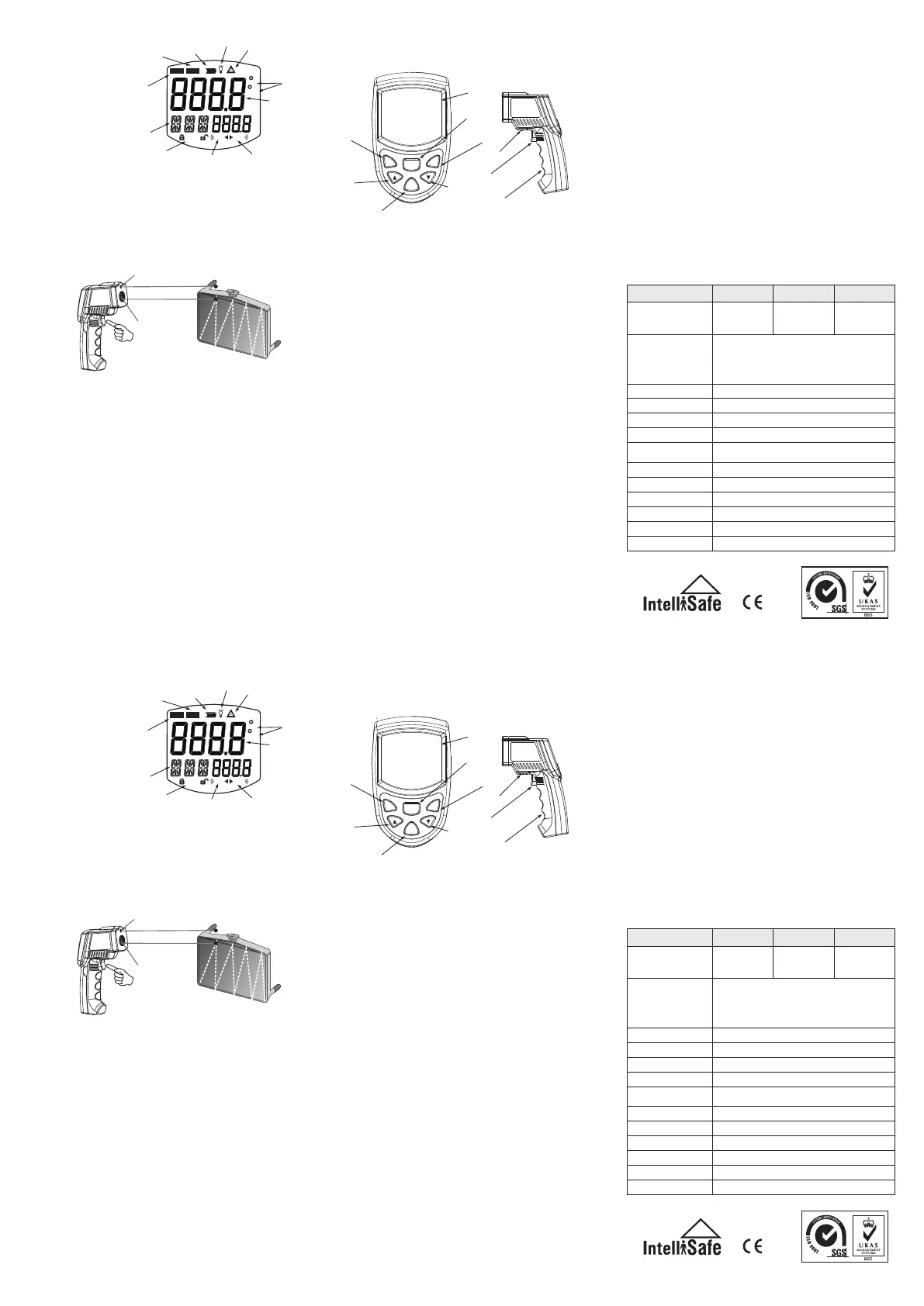
LCD display:
A measuring reading
B measuring unit G data hold icon
C laser on icon H mode indicator
D back light on icon I data storge / read icon
E battery power icon J low temperature alarm icon
F scanning icon K hight temperature alarm icon
2. Locating a hot spot: To find a hot spot aim the
thermometer outside the area of interest, then
scan across with up and down motions unitl you
locate the hot spot.(please turn on the laserto for
accurate measuring)
3. Diagram description
(1) Trigger: When turn on LCD display VER XX
software version for 1 sec. And turn to di-splay
reading with SCAN icon. Release the trigger,
display reading with HOLD icon for 7 sec. Built
in auto power off in 30sec.
(2) Laser / back light button: when back light turn
Attention:
Red laser point only position the general direction the
detection hole is the main parts measure the temperature
Red laser point
detection hole
(Figure 3)
on , any operations will remain back lig-ht for
10 sec. LCD indicate on/off status.
Repeatability
Response time
Spectral response
Emissivity
Relative humidity
Storage temperature
Weight/Dimensions
Power
Battery life (Alkaline)
Distance to Spot Size
Specifications
Temperature
range
Accuracy
Ambient operating
range
-20 to 60℃ (-4 to 140℉) without battery
100℃(212℉) to 600℃(1112℉)±2℃or±2%
0℃(32℉) to 100℃(212℉) ±2℃or±2%
-50℃(-58℉)to 0℃(30℉) ±3℃or ±3%
whichever is greater
1% of reading or 1℃
500 mSec, 95% response
8-14 um
0.10 to 1.00 adjustable (pre-set 0.95)
0 ~40℃ (32 ~ 104℉)
170G ; 175*100*49mm
Laser Models:12 hrs
12:1
-50℃~600℃
-58℉~1112℉
10-95% RH noncondensing
9v Alkaline or NiCd battery
AS842A AS852B
-50℃~750℃
-58℉~1382℉
AS862A
-50℃~900℃
-58℉~1652℉
(Figure1)
h. EMS: Emissivity setup--press 5 keys for emissivity
settings, press 4 key to save setup and back to
normal status.
(7) LCD
(8) Battery door clip
(9) Battery door: When replace battery door, please
press battery door clip and pull the battery door.
(10) Clesius / Fahrenheit switch: Please open battery
and push the slide switch for con-vertsion
Maintenance
1) Lens cleaning: Blow off lose particles using
clean compressed air. Gently brush remaining
debris away with a moist cotton cloth.
2) Case cleaning: Clean the case with a damp
sponge/cloth and mild soap.
Note:
1) Do not use solvent to clean lens.
2) Do not submerge the unit in water.
(3)—(6) key functions: press 3 key, LCD subdis-
play blinks MAX-MIN-DIF-AVG-HAL-LAL-
STO segment(only main display means normal
measuring mode) press 4 key to enter.
a. MAX: measuring maximum temperature
b. MIN: measuring minimum temperature
c. DIF: Basic on the reading before press 4 key,
compute the difference of current reading.
d. AVG: measuring average temperature
e. HAL: high temperature alarm--when selected
HAL, press 5 keys to set high temperature alarm
trigger and confirmed by pressing 4 key. When
reading over trigger, LCD display HI icon with
BiBi audio sounds.
f. LAL: low temperature alarm--when selected
LAL, press 5 keys to set low temperature alarm
trigger and confirmed by pressing 4 key. When
reading over trigger, LCD display LOW icon with
BiBi audio sounds
g. STO: data storage--when selected STO, lock &
DATA & 1---indicator will shown when press 4 key.
After temperature read out press 6 key to store,
then 2---memory unit will be shown. There 12
groups memory unit available. To recall the stored
data in normal measuring mode by press-ing 6 key,
remove all data by pressing 6 keys for 2 secretary.
A
B
C
D
E
F
G
C
F
HO LD
SC AN
LOW H IGH
DATA
H
J
I
K
(Figure4)
2
SET
STO /CAL
LASER
BACKL IT
MOD E
1
7
5
6
5
8
4
3
(Figure3)
9
Quick start instruction
LCD display:
A measuring reading
B measuring unit G data hold icon
C laser on icon H mode indicator
D back light on icon I data storge / read icon
E battery power icon J low temperature alarm icon
F scanning icon K hight temperature alarm icon
2. Locating a hot spot: To find a hot spot aim the
thermometer outside the area of interest, then
scan across with up and down motions unitl you
locate the hot spot.(please turn on the laserto for
accurate measuring)
3. Diagram description
(1) Trigger: When turn on LCD display VER XX
software version for 1 sec. And turn to di-splay
reading with SCAN icon. Release the trigger,
display reading with HOLD icon for 7 sec. Built
in auto power off in 30sec.
(2) Laser / back light button: when back light turn
Attention:
Red laser point only position the general direction the
detection hole is the main parts measure the temperature
Red laser point
detection hole
(Figure 3)
on , any operations will remain back lig-ht for
10 sec. LCD indicate on/off status.
Repeatability
Response time
Spectral response
Emissivity
Relative humidity
Storage temperature
Weight/Dimensions
Power
Battery life (Alkaline)
Distance to Spot Size
Specifications
Temperature
range
Accuracy
Ambient operating
range
-20 to 60℃ (-4 to 140℉) without battery
100℃(212℉) to 600℃(1112℉)±2℃or±2%
0℃(32℉) to 100℃(212℉) ±2℃or±2%
-50℃(-58℉)to 0℃(30℉) ±3℃or ±3%
whichever is greater
1% of reading or 1℃
500 mSec, 95% response
8-14 um
0.10 to 1.00 adjustable (pre-set 0.95)
0 ~40℃ (32 ~ 104℉)
170G ; 175*100*49mm
Laser Models:12 hrs
12:1
-50℃~600℃
-58℉~1112℉
10-95% RH noncondensing
9v Alkaline or NiCd battery
AS842A AS852B
-50℃~750℃
-58℉~1382℉
AS862A
-50℃~900℃
-58℉~1652℉
 Loading...