EasyManua.ls Logo

Smarter SMART MIG-250 - User Manual

Smarter SMART MIG-250
9 pages
Print Icon
To Next Page IconTo Next Page
Loading...
IMPORTANT
Read this Owner's Manual Completely before attempting to use this equipment. Save
this manual and keep it handy for quick reference. Pay particular attention to safety
instructions we have provided for your protection. Contact your distributor if you do not
fully understand this manual.
OPERATORS' MANUAL
HIGH TECH PROFESSIONAL MIG/MAG MACHINE
SMART MIG-250
SMART MIG-350
RoHS
C O M P L A N T
www.smarter-welding.com
CHINA:
USA
BRASIL
ADD.:Chengxi Industrial Zone, Wenling City,
Zhejiang Province, China
PC.:317525
URL:www.smarter-welding.com
Sales Department
Tel:+86-576-86191288 86191296
Fax:+86-576-86191290 86901116
E_mail:sales@zjwanshun.com
Wenling Wanshun Electromechanics
Manufacture Co.,Ltd.
12195 Harley Club Drive
Ashland, VA 23005
Tel:804.798.8588
Fax:804.798.0338
E-mail:toby@usesmartertools.com
URL:www.usesmartertools.com
RUA DR OLIMPIO CARR RIBEIRO 26 ,
VILA CALIFORNIA C.E.P 04775-120 S PAULO SP BRASIL
URL:www.smarter-welding.com
www.smarterbrasil.com.br
Tel:(0055-11)3432-1557.3433-0076.3433-1890
GSM:96831-0180. (51)8156-2026
E-mail:smartertoolsbrasil@hotmail.com
Question and Answer IconNeed help?

Do you have a question about the Smarter SMART MIG-250 and is the answer not in the manual?

Summary

Safety Instructions

Personal Protection

Ensures user safety from arc welding hazards like burns, UV radiation, and flying debris during operation.

Fire Prevention Measures

Guidelines to prevent fires caused by welding sparks, hot metal projections, and flammable substances.

Electric Discharge Safety

Precautions against electric shock, including proper insulation, dry conditions, and grounding.

Ventilation Requirements

Ensures adequate airflow to remove welding fumes and prevent respiratory irritation.

Equipment Maintenance Safety

Procedures for safe maintenance, emphasizing disconnection from power and qualified personnel.

Welding;Cutting Equipment Use

Safe operation guidelines for welding and gas cutting equipment, including pressure and hose checks.

Gas Cylinder Handling

Safety instructions for stocking, using, and transporting compressed gas cylinders.

Product Description

Technical Specifications

Installation and Operation Guide

Electrical Schematics

Spare Parts List

Maintenance and Troubleshooting

Product Warranty Terms

Overview

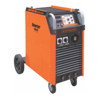
The document provides an operator's manual for the SMART MIG-250 and SMART MIG-350 High Tech Professional MIG/MAG Machines, manufactured by Wenling Wanshun Electromechanics Manufacture Co., Ltd. These machines are designed for arc welding under protective gas, utilizing inert gases (MIG process) or active gases (MAG process).

Function Description

The SMART MIG-250 and SMART MIG-350 are professional MIG/MAG welding machines. They are equipped with an integrated wire feeder, a coil holder, and either a 2-roll motor (for Smart MIG-250) or a 4-roll motor (for Smart MIG-350), all protected by a removable cover. These machines are suitable for welding with various protective gases:

  • Carbon dioxide (CO2) for steel welding.
  • 80-85% Argon + 20-15% CO2 for steel welding.
  • 95-98% Argon + 5-2% CO2 for stainless steel welding.

Important Technical Specifications

Smart MIG-250

  • Standard: EN60974-1
  • Output Current/Voltage Range: 25A/15.3V - 250A/26.5V
  • Duty Cycle (X):
    • 40%: 250A / 26.5V
    • 60%: 205A / 24.3V
    • 100%: 160A / 22V
  • Input Voltage (U1): 400V
  • Max Input Current (I1max): 14A
  • Effective Input Current (I1eff): 8.9A
  • Protection Class: IP21S
  • Insulation Class: H
  • Adjustment Positions: 12
  • Wire Diameter: 0.8-1.2 mm
  • Weight: 85 kg
  • Dimensions: 91 x 50.5 x 81 cm

Smart MIG-350

  • Standard: EN60974-1
  • Output Current/Voltage Range: 35A/15.8V - 350A/31.5V
  • Duty Cycle (X):
    • 50%: 350A / 31.5V
    • 60%: 320A / 30V
    • 100%: 250A / 26.5V
  • Input Voltage (U1): 230V or 400V
  • Max Input Current (I1max): 40A (230V), 23A (400V)
  • Effective Input Current (I1eff): 28A (230V), 16A (400V)
  • Protection Class: IP21S
  • Insulation Class: H
  • Adjustment Positions: 28
  • Wire Diameter: 0.8-1.2 mm
  • Weight: 108 kg
  • Dimensions: 97 x 56.5 x 89 cm

Usage Features

The manual emphasizes safety prescriptions for arc welding generators, including personal protection, fire prevention, electric discharge prevention, proper ventilation, and safe handling of gas tubes.

Installation and Operation:

  • Machines must be installed in clean, dry places, free from dust, humidity, and flammable products.
  • Before connecting the primary cable, verify the mains voltage (3x230V or 3x400V). The machine is typically set to 3x400V but can be prepared for other voltages upon request.
  • A strong earth connection is recommended to avoid health risks.
  • Gas or water hoses must be checked for leaks when connected.
  • The torch and earth cable must be well-tightened to ensure good welding quality.
  • Wire Coil Positioning: Ensure the wire coil's hole is correctly positioned on the spindle to maintain the breakage system.
  • Wire Feeder Rolls: The wire feeder rolls and torch tip must match the wire diameter.
  • Wire Feeding: Manually guide the wire a few centimeters through the rolls and wire guide. Close the traction levers, ensuring the wire is well-positioned on the roll end.
  • Roll Pressure Regulation: Adjust pressure to the minimum to prevent wire deformation, ensuring the wire flows without sliding.
  • Wire Coil Breakage System: Regulate the breakage system by actuating the screw so that the wire coil stops rotating simultaneously with the motor.
  • Welding Process: Turn the main switch to ON, press the torch trigger, and regulate gas flow between 6 and 10 liters/min during welding.

Maintenance Features

MIG machines require periodic inspection and cleaning, especially in dusty or humid environments.

  • General Maintenance Steps:

    • Disconnect the machine from the mains supply.
    • Remove lateral covers.
    • Clean all dust and humidity with low-pressure, dry air.
    • Retighten all electrical contacts (bolts and nuts).
    • Periodically inspect the torch, which is subjected to high temperatures during operation. Refer to the torch's user manual for detailed maintenance information.
  • Troubleshooting Guide:

    • Machine does not weld when connected to main switch:
      • Cause: Failure on main voltage. Proceeding: Check main supply voltage and protective electrical circuits.
      • Cause: Blown command circuit fuses. Proceeding: Check and replace, if necessary.
      • Cause: Interruption of the primary cable. Proceeding: Check and replace, if necessary.
    • Irregular advance of wire:
      • Cause: Low pressure of rolls. Proceeding: Adjust the pressure system.
      • Cause: Wire guide damaged or in bad condition. Proceeding: Clean properly and replace, if necessary.
      • Cause: Diameter rolls do not match with wire diameter. Proceeding: Replace rolls with the adequate diameter.
      • Cause: Wire coil breakage system too much tightened. Proceeding: Adjust with the adequate pressure.
      • Cause: Damaged wire or wire coil. Proceeding: Check and replace, if necessary.
    • Porosity in welding melt:
      • Cause: Gas failure. Proceeding: Check bottle pressure and control gas flow.
      • Cause: Solenoid valve blocked. Proceeding: Check and, if necessary, disassemble for cleaning.
      • Cause: Too much wind blowing through the welding zone. Proceeding: Protect the welding zone from wind or adjust up the gas flow.
      • Cause: Torch nozzle blocked or in bad condition. Proceeding: Clean or replace the torch nozzle.
      • Cause: Welding piece too dirty, wet or greased. Proceeding: Clean the welding surfaces.
    • Failure on welding quality:
      • Cause: Defective electrical contact of earth clamp or torch. Proceeding: Tighten the earth clamp and torch. Check the earth cable.
      • Cause: Failure on electrical contactor. Proceeding: Disassemble and clean electrical contactor. If not possible, replace contactor.
      • Cause: Damaged rectifier bridge. Proceeding: Check bridge and replace, if necessary.
    • Wire feed motor does not run:
      • Cause: Failure of the wire feed motor electrical supply. Proceeding: Check and replace, if necessary, the wire feed motor fuse. Check the electrical insulating of the wire feed motor.
      • Cause: Failure of wire feed motor brushes. Proceeding: Replace brushes.

Warranty Information

All SMARTER products are guaranteed for 12 months against manufacturing defects detected upon receipt. SMARTER reserves the right to alter product characteristics for improvements. Depending on the problem, SMARTER may choose to repair or replace defective equipment. Warranty replacements or maintenance are handled by Authorized Technical Service within the guarantee deadlines. Travel fees may apply for repairs done where the machine is installed.

The warranty does not cover:

  • Wear on finish, parts, or parts damaged by heavy use or exposure to adverse conditions (rain, humidity, high temperatures, freezing).
  • Damage caused during transport and assembly if not implemented by SMARTER or designated professionals.
  • Misuse, undue effort, or use different from the company's intended purpose for the product, or defects caused by attrition or institutional use for products not explicitly indicated.
  • Problems caused by non-compliance with manual instructions, adaptations, or alterations.
  • Mistreatment, neglect, cleaning, or maintenance contrary to company instructions.
  • Damage caused by repairs hired by the consumer and not by SMARTER Authorized Technical Service.
  • Damage caused by accidents, falls, short circuits, lightning, improper power connections, flood, natural phenomena, pest attacks, or natural causes.

Smarter SMART MIG-250 Specifications

General IconGeneral
BrandSmarter
ModelSMART MIG-250
CategoryWelding System
LanguageEnglish

Related product manuals