EasyManua.ls Logo

smartmicro UMRR-0A User Manual

smartmicro UMRR-0A
19 pages
To Next Page IconTo Next Page
Page #1 background imageLoading...
Page #1 background image
CONFIDENTIAL AND PROPRIETARY
The Information contained in this document shall remain the sole exclusive property of s.m.s smart microwave sensors GmbH and shall not
be disclosed by the recipient to third parties without prior consent of s.m.s smart microwave sensors GmbH in writing.
UMRR-0Axxxx Type31 Operational Description.docx Version 1 I Page 1 of 19 I August 22, 2013
Project Documentation | UMRR-0A Radar Sensor Documentation
Project Number:
...
SMS Project Number:
Project Title:
General Purpose Radar Sensor
Keyword(s):
UMRR-0A radar sensor, type 31 antenna
Date:
August 22, 2013
Document:
UMRR-0Axxxx Type31 Operational Description.docx
Version:
1
Question and Answer IconNeed help?

Do you have a question about the smartmicro UMRR-0A and is the answer not in the manual?

smartmicro UMRR-0A Specifications

General IconGeneral
Brandsmartmicro
ModelUMRR-0A
CategoryAccessories
LanguageEnglish

Summary

Abbreviations Reference

List of Technical Abbreviations

Provides a glossary of acronyms and their full meanings used throughout the document.

Document Introduction

Overview of UMRR Radar Sensor Documentation

Introduces the document as a concise overview of the UMRR radar sensor.

General Description of UMRR Sensor

UMRR Sensor Functionality and Components

Details the UMRR sensor's primary task, its two-board structure, and key internal components.

UMRR Transmit Signal Characteristics

Specifies the operating frequency band, bandwidth, maximum transmit power, and antenna polarization.

UMRR Operational Startup Behavior

States that the transmit (TX) and receive (RX) functions commence immediately upon device power-up.

UMRR Hardware Overview

UMRR Sensor Front View Illustration

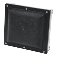
Presents a visual representation of the UMRR sensor's front housing.

UMRR Sensor Physical Dimensions

Displays detailed measurements of the sensor from front, top, left, and right perspectives.

UMRR Connectivity

UMRR Sensor Connector Pin Assignment

Outlines the pin configuration of the 8-pin circular connector used for sensor interfacing.

UMRR Data Interfaces

UMRR CAN Bus Communication Protocol

Explains the CAN data interface, its compliance with CAN 2.0B standard, and its bidirectional capabilities.

UMRR CAN Bit Timing Configuration

Lists the specific bit timing parameters (Baud Rate, Tseg1, Tseg2, Tsjw) for the CAN interface.

UMRR RS485 Serial Communication

Describes the RS485 interface, its predefined speed, and the structure of its data messages.

UMRR Transceiver Circuit Schematics

Provides schematic diagrams illustrating the DSP board's CAN and RS485 transceiver connections.

UMRR Application Scope

UMRR Radar Sensor Designated Uses

Outlines the suitability of the UMRR for applications requiring distance and speed measurement of large objects.

UMRR Regulatory Compliance

USA FCC Compliance Statement

Confirms adherence to FCC Part 15 regulations and specifies operational conditions for the United States.

Canada Industry Canada Compliance

States compliance with Industry Canada RSS-310, including operational conditions for Canada.