WARNING:
Do not mount the hydraulic pump or tray assembly in any location that is not well
ventilated. External heat sources elevating the hydraulic fluid and/or the generator
temperature will result in premature wear and degraded system performance and void
the system’s warranty.
7. The tray assembly must be mounted in a position that is higher than the pump. If the
pump inlet hose is 10’ in length or less, the tray and reservoir assemblies must be a
minimum of 12” higher than the pump. If the pump inlet hose is longer than 10’,
elevate the tray and reservoir assemblies an additional 12” for every additional 10’ of
pump inlet hose length. See below for examples of minimum tray assembly
elevations above the pump:
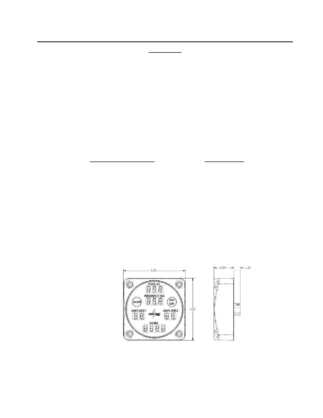
8. Locate a position to mount the SPS Command & Control Center. The ideal location
for the Command & Control Center will be in an area that is easily seen and accessed
by the generator operator. When the generator system is in use, the Command &
Control Center will continuously show the status of the generator, including faults
(warnings) if they occur. The Command & Control Center can also be used to engage
and disengage the generator. The Command & Control Center is water sealed, and
operates on low voltages so pump house mounting is permissible. A 15 ft. water
sealed harness is provided to connect the Command & Control Center to the system
controller mounted within the generator tray assembly. See Figure 6 for the
dimensions of the Command & Control Center.
Figure 6 - Command & Control Center, P/N 1500047C