8. Connect the vehicle’s breaker panel to the generator output. The generator is pre-
wired to supply 120/240 VAC, with the generator frame bonded to ground. Route the
generator output conduit/wiring to the breaker panel, and carefully cut the conduit to
length without cutting the wire insulation. A conduit connector has been provided to
connect the conduit to the breaker panel. Connect the (4) four generator output wires
to the breaker panel as follows (see Figure 2 for electrical schematic and wiring
diagram):
Phase A: Black wire (120/115 VAC)
Phase B: Red wire (120/115 VAC)
Neutral: White wire
Ground: Green wire
To completely utilize the generator’s output capabilities, the 120/115 VAC loads must
be equally divided between the generator’s two main windings. Before wiring the
vehicle, calculate the wattage of each 120/115 VAC load that will be connected to the
generator. Next, create two groups of loads based on total wattage (add the
individual wattage of each load together). Exchange loads between the two groups
until the total wattage of the two groups is as close as possible to being equal. Wire
the system with one group connected to Phase A (BLACK) and neutral, with the other
group connected to Phase B (RED) and neutral.
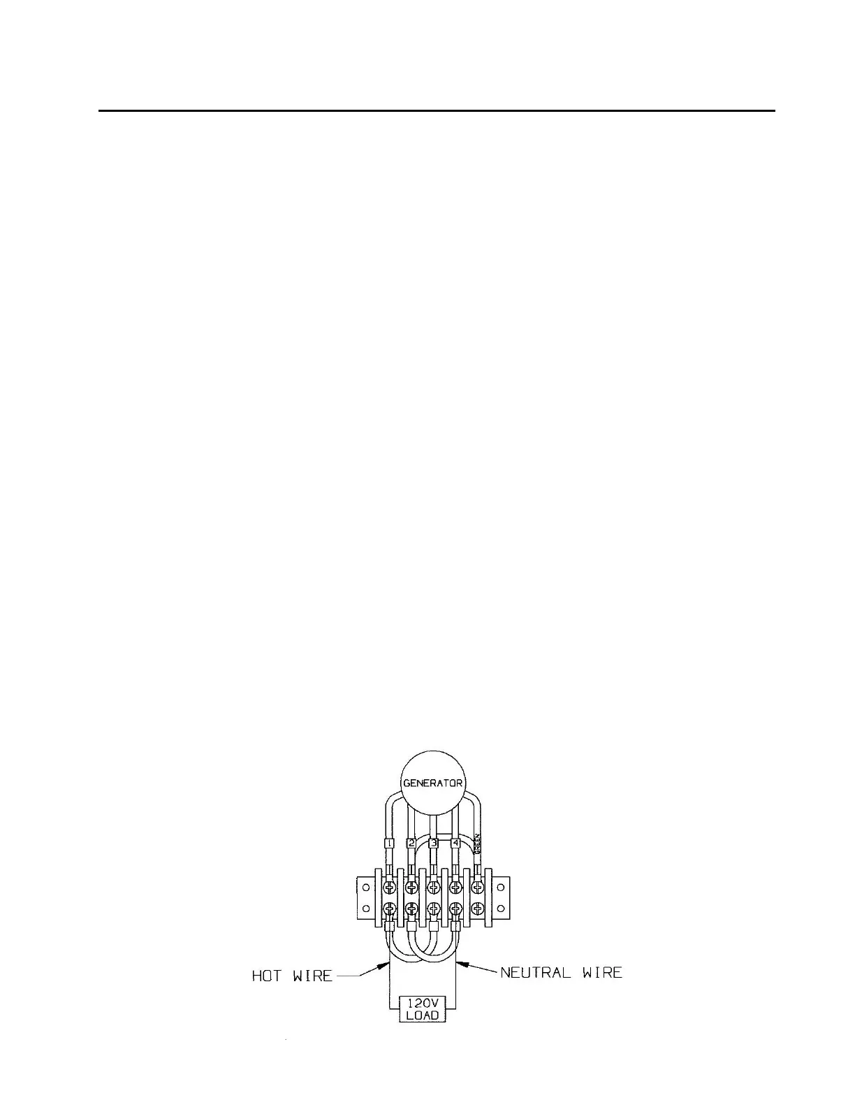
ALTERNATE CONFIGURATION: 120/115 VAC only: If the application requires
120/115 VAC only, the generator terminal strip should be configured as depicted
below (Figure-12). This method ensures balanced loading of the generator, fully
optimizing the system’s capabilities. Make the following wire connections at the
terminal strip:
a) place one jumper between wire 1 and wire 3.
b) place the second jumper between wire 2 and wire 4.
c) connect the phase wire from the breaker box to either wire 1 or wire 3.
d) connect the neutral wire from the breaker box to either wire 2 or wire 4.
e) connect the ground wire from the breaker box to the green wire.
 Loading...