Do you have a question about the Smitec FLXMOD CPC 04 Series and is the answer not in the manual?
Covers general safety advice, emphasizes reading the manual, and contact for interpretation difficulties.
Provides guidance on using appropriate tools and safety measures during handling and assembly to prevent injury.
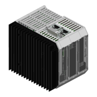
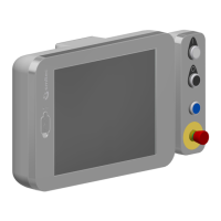
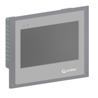
Visual representations of the CPC 04XX module, illustrating its physical appearance and key external features.
Details operating conditions such as temperature, humidity, and altitude limits.
Lists electrical parameters including voltage, current, power consumption, and ripple.
Covers physical attributes such as fastening method and weight of the module.
Provides detailed diagrams showing the physical measurements of the module from various views.
Shows the dimensional measurements of the CPC 04XX module from the front perspective.
Presents the dimensional measurements of the CPC 04XX module from the rear perspective.
Details the dimensional measurements of the CPC 04XX module from the top perspective.
Illustrates the dimensional measurements of the CPC 04XX module from the bottom perspective.
Details the core hardware components and features of the CPC 04XX industrial PC.
Lists the fundamental hardware specifications common to all CPC 04XX models.
Highlights specific hardware features and connections for the CPC 0401 model.
Outlines specific hardware features and connections for the CPC 0402 model.
Lists the various order codes available for different configurations and models of the CPC 04XX.
Details the optional accessories and compatible items for the CPC 04XX industrial computers.
Identifies connectors and LEDs located on the front panel of the CPC 04XX module.
Specifies the function of connection interfaces such as CFast and micro SD sockets.
Describes the meaning and behavior of the power and status LEDs on the module.
Details the DVI-I connector outputs on the top, differentiating between HMI and DVI-D models.
Specifies the function of the HMI and DVI-D ports on the DVI-I connector.
Illustrates the connections on the bottom of the CPC 04XX module for the CPC 0401 model.
Lists and describes the ETH, COM, USB, and 24VIN connections on the bottom view.
Details the connections on the bottom of the CPC 04XX module for the CPC 0402 model.
Explains the ETH1, ETH2, USB, and 24VIN connections for the CPC 0402.
Describes the 24VDC power supply connector, its features, and pinout.
Details the module's USB port, its type (USB 3.0), and compatibility.
Explains the Ethernet ports, their speeds, and RJ45 connectors on the module.
Shows the Ethernet port configuration and associated LEDs for the CPC 0401 model.
Illustrates the Ethernet ports (ETH1, ETH2) and their LEDs for the CPC 0402 model.
Details LED behavior for communication speed signaling on the CPC 0401 Ethernet port.
Explains the meaning of the 'S' LED for Ethernet speed (10, 100 Mbps, 1 Gbps).
Describes the function of the 'A' LED for Ethernet port connection and activity.
Details LED behavior for communication speed signaling on CPC 0402 Ethernet ports.
Explains the 'S1' and 'S2' LEDs indicating Ethernet communication speed for CPC 0402.
Describes the 'A1' and 'A2' LEDs indicating Ethernet connection and communication status for CPC 0402.
Details the RS485 serial port, its RJ45 connector, pinout, and network connection.
Describes the location and purpose of the CFast and micro SD memory sockets.
Explains the function of the reset button and provides a warning regarding its use.
Details the mounting procedure of the CPC 04XX module onto a DIN rail and its grounding.
Specifies the need for proper environmental conditions, including cooling, for optimal operation.
Guides on making correct power supply, earth, and peripheral connections.
Explains the advantages and usage of the CFast card as a storage device.
Details the benefits and usage of the Micro SD card for data storage.
Describes the sequence and priority of devices used for system boot-up.
Provides step-by-step instructions for safely replacing the real-time clock backup battery.
Details CMOS setup parameters, their protection, and behavior upon battery failure.
| Brand | Smitec |
|---|---|
| Model | FLXMOD CPC 04 Series |
| Category | Industrial PC |
| Language | English |