Do you have a question about the SmoothTalker Mobile X6 4G LTE and is the answer not in the manual?
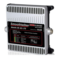
Details the wireless booster's extreme power and supported network technologies like 2G, 3G, 4G, and LTE.
Lists the specific frequency bands (e.g., 700MHz, 850MHz, 1700/2100MHz) covered by the signal booster.
Illustrates the setup for a mobile wireless system within a vehicle using the booster.
Describes an alternative configuration for using the booster in a stationary desktop environment.
Provides instructions on connecting antennas and positioning the booster for optimal performance.
Emphasizes using only the included power supply to prevent damage and voiding the warranty.
Explains how LEDs indicate the booster's operating gain state and signal reception.
Details reasons for reduced gain, such as high signal levels or loop oscillation between antennas.
Describes LED flashes and their relation to dB reduction in signal gain.
Explains the Green LED's role in indicating loop oscillation status and gain reduction.
Details the Orange LEDs' indication of specific frequency bands and operational status (ON/OFF/Flashing).
Summarizes LED indicators for gain reduction, including solid ON, flashing, and OFF states.
Covers compliance with FCC NPS and the booster's fixed, non-programmable safeguard features.
| Model | SmoothTalker Mobile X6 4G LTE |
|---|---|
| Category | Extender |
| Connectivity | 4G LTE |
| Network Technology | 4G LTE |
| Device Name | SmoothTalker Mobile X6 4G LTE |
| Frequency | 1700MHz, 1900MHz |