C
Fiber optic connection:
Take care when mating connectors with the units, all
beroptic connectors are polarized and should never be
forced.
Fiber cables
Ready made Fiberoptic cable assemblies, terminated
with IP67 rated, polarized, Huber&Suhner Q-ODC con-
nectors, are normally ordered from SMW with the system.
They available in several standard lengths: 50, 100,
150 and 200 m and can also be supplied in customized
lengths and with other terminations like
Q-ODC to FC-APC, Q-ODC to LC-APC or
Q-ODC to SC-APC.
A
RF / L-band connectors
Your units are equipped with 4 L-band connections. Con-
nectors can be type F, type N or type SMA depending on
your system specic conguration.
• On the Transmitter Tx, connect your RF signal sour-
ces such as LNBs or input signal for BUCs.When
congured for LNBs DC power from the DC power
input (D, g 1) is fed through to all 4 RF / L-band
connectors for powering LNBs. Rating is max 600 mA
per port, individually autofused, short circuit protected
• On the Receiver Rx, connect your RF signal receiver
for SAT signals from LNBs or your BUC input.
• Use an appropriate torque wrench for tightening the
connectors.
B
10 MHz reference connection, return path
(optional)
If your units are equipped with the optional 10 MHz return
channel connection:
The return channel transmitter uses a dierent wave-
length laser than the WDM laser used for the L-bands. As
the name ”return path” suggests, it transmits the 10 MHz
reference signal from the Receiver Rx to the Transmitter
Tx enabling the 10 MHz reference source to be located
near the RF receiver.
• On the Receiver Rx, connect your external 10 MHz
reference to the RF connector (C, g. 2)
• On the Transmitter Tx, connect your LNBs’ External
reference port to the RF connector (C, g. 2)
• Use an appropriate torque wrench for tightening the
connector.
Cleaning is essential!
The information carrying ber core is 9 µm in
diameter, approx. a tenth of the human hair, so
ber-optic connections are very sensitive to
impurities on the ber ends. Impurities such as dust,
bers from clothes, ngerprints etc will result in
degradation of system performance or system error.
Cleaning with an appropriate cleaning tool, such as
a “Click Pen”, is strongly recommended EVERY
TIME before reconnecting a beroptic cable.
The IBC brand “Click Pen” should be a part of any
installers’ tool kit and is available from SMW (p/n
280505-01) or can purchased locally from a well
stocked Fiberoptic supplier.
Please also refer to Huber&Suhner Application Note
”Cleaning of Fiber-optic connectors” which can be
ordered free of charge from SMW.
5
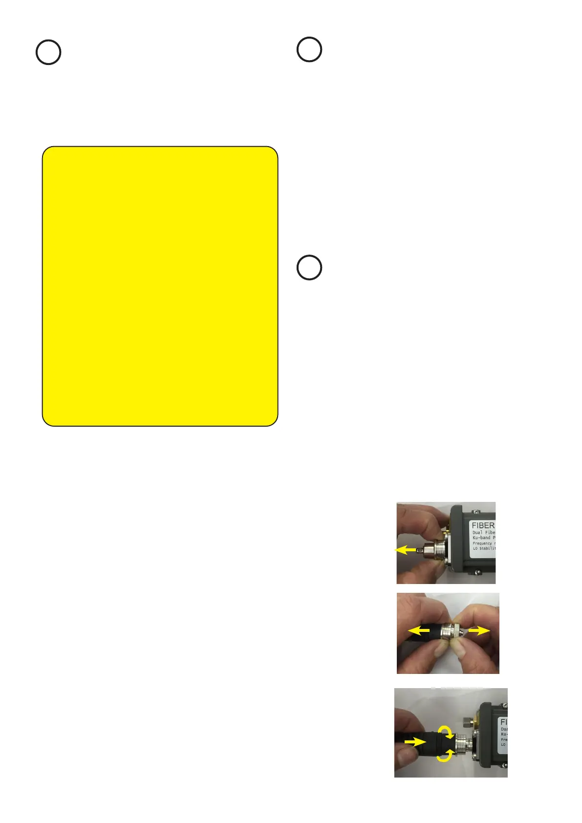
Fig. 5
Fig. 6
Connecting
Take care when mating connectors with the units, Q-ODC
connectors are polarized and should never be forced on.
MATE: Push cable plug gently into connector, rotate (a)
to nd keying position, push connector (b) until ”click” to
mate (Fig. 7).
UNMATE: Pull coupling ring to unmate(Fig. 5,6).
Fig. 7
(b)
click
(a)
 Loading...