ATI520J – Portable Cable Terminal Swager Operating and Maintenance Manual
Page 10 of 12
INSPECTION AND CHECK OUT PROCEDURE
1. Check the gap between the yoke, cap and housing. All joints must be tight.
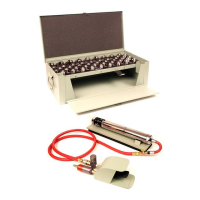
2. Place the tool on the base plate ATI520CBP.
3. To check the swager, select a pair of ATI520CDB-5 dies. Clean the dies and apply a coat of light oil.
4. Insert the rear die into the yoke with the keyway facing down and shank facing toward the rear of the tool. Slide
the die back in order to clear the opening for insertion of the forward die. Insert the forward die, with the shank
facing forward, and slide it into the forward position.
5. Connect the swager airline to the foot control valve.
6. Connect the foot control valve to a regulated pressure airline. IMPORTANT: the Swaging tool must operate on
90 psi of regulated air. Use a minimum 3/8” I.D. hose.
7. Check the lubricator for oil (See Figure 6, Page 4).
8. Read and familiarize yourself with the swager operating instructions on Page 4.
9. Swage an MS20663-5 double shank ball type terminal to a 5/32” cable for 30 seconds, noting whether the swager
operates smoothly or erratically. If a malfunction is indicated, or terminal is not swaged to the dimensions shown
in the chart of Page 5, reject the power unit.
!!!!! CAUTION !!!!!
DO NOT OPERATE THIS TOOL WITHOUT SWAGING DIES IN PLACE.
DO NOT PLACE HANDS IN THE DIE CHAMBER AT ANY TIME.
DO NOT OPERATE THIS TOOL WITHTOUT THE SAFETY GUARD IN PLACE.
** CUSTOMER ADVISORY NOTE **
Please note that the Piston ATI520BR-3 can be inadvertently installed backwards in the Swaging Tool. The piston has a
45 chamfer on one end that is designed to match the shank diameter of the swaging die. If the un-chamfered end is
used against the swaging die, the piston will become swollen and distorted. This action will significantly affect the
performance of the swager and could cause permanent damage to the swaging tool.
ATI520 SERIES
SWAGING DIE
 Loading...