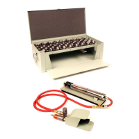
ATI520J – Portable Cable Terminal Swager Operating and Maintenance Manual
Page 9 of 12
POWER UNIT REMOVAL
After the cap has been removed, as shown in Figure 13, the
entire power unit and spring can be extracted from the housing
by pulling it out as shown in Figure 14.
POWER UNIT BREAKDOWN
1. Refer to Figure 15 and parts reference drawing on
Page 11.
2. Remove the spring, lock ring and piston from the
barrel.
3. Place the barrel in a vise. Use flats for clamping.
4. Use a 2” open-end wrench to remove the house from
the barrel, turning counter-clockwise.
5. Slide the valve assembly out of the barrel.
SWAGING TOOL ASSEMBLY PROCEDURE
1. Clean and check all detail parts of the swaging unit. Replace defective parts where needed.
2. Place the ATI520C-18 pins into the yoke and install the ATI429DR-6 rings (2 required).
3. Screw the yoke and housing together and tighten (See Figure 12). On the threads, use LOCTITE Grade AV-mil-
S-22473B – Federal Stock number 8030-081-2337. **THREADS MUST BE CLEAN AND DRY BEFORE
APPLYING LOCTITE**
4. After reassembly of the power unit, apply a light coat of grease to the “U” packer ATI520C-5. Hold the power unit
Assembly in the vertical position with the “U” packing down and position the ATI520CJP-2 saw tooth lock ring so
that there is a full face to face engagement of at least one tooth in the ATI520CJP-1 housing. Slide the spring
onto the barrel of the power unit (do not allow the saw tooth lock to become disengaged). Slide the power unit
and spring into the housing and yoke assembly.
5. Install “O” ring ATI520C-4 on the ATI520J-3 Cap after coating with grease.
6. Holding the power unit securely in the housing, apply LOCTITE (Grade AV-mil-S-22473B – FSH 8030-081-2337
on the threads of the cap and assemble (See Figure 13). **THREADS MUST BE CLEAN AND DRY BEFORE
APPLYING LOCTITE**
7. Using an open-end wrench, attach the ATI520CH airline securely to the ATI520J-3 Cap.
8. Allow the swager to impact against the dies for five minutes.
9. Re-tighten the entire thread assembly.

 Loading...