14
4-1
4-2
3
1
2
4
5
3a
6
8
2
1
9
7
3b
1
2
3
4-3
10
Layout
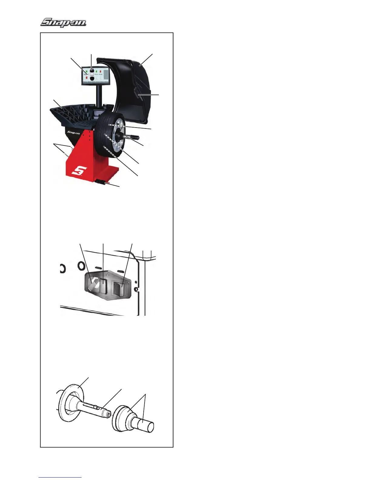
4.0 Layout
Refer to Figure 4-1.
Functional description of the unit:
1.
Display
Refer to Chapter 4.1.
2. Input panel
Refer to Chapter 4.1.2
3a
Internal gauge arm
3b External Detector - Sonar
4. Flange
5. Stub shaft
6. Weight compartments
7. Storage areas for cones and hub nuts
8. Wheel guard
9. Control pedal (Brake / Power Clamp)
10. Laser Pointer (F 4.6)
Refer to Figure 4-2.
1.
Mains switch (ON/OFF)
2. Fuse holder
3. Power inlet
Refer to Figure 4-3
Power clamping device
1 Basic body of clamping device (Flange)
2
Chuck and clamping jaws
3 Clamping sleeve and head