76
5-36
5-37
5-38
5-39
5-40
26
26
Operation
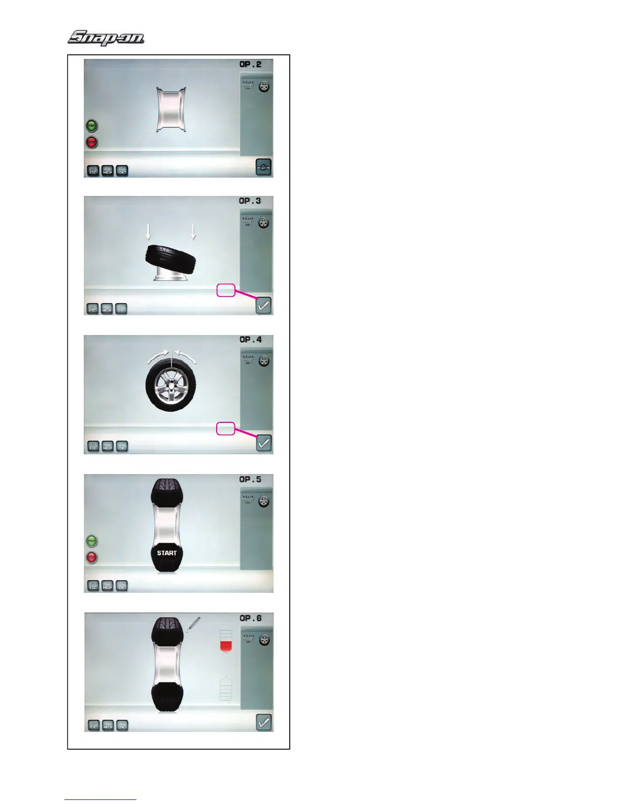
Fig. 5-36 OPTIMISATION “OP.2”
START is signalled on the screen.
— Spinn the wheel.
A compensation run is performed.
The screen “OP.3” as shown in Fig. 5-37 is displayed.
Fig. 5-37 OPTIMISATION “OP.3”
—
Mount the tyre correctly on the rim and infl ate
to specifi ed infl ation pressure (make sure the
mounting guide rim of the tyre is correctly seated).
— Confi rm by pressing menu key 26.
The OPTIMISATION “OP.4” screen (Fig. 5-38) is
displayed.
Fig. 5-38 OPTIMISATION “OP.4”
(fi rst measuring run of tyre/rim assembly)
— Clamp the wheel on the balancer.
— Readjust the wheel such that the valve is exactly
perpendicular to and above the main shaft.
— Enter the valve position by pressing menu key 26.
The OPTIMISATION “OP.5” screen (Fig. 5-39) is
displayed.
Fig. 5-39 OPTIMISATION “OP.5”
START is signalled on the screen.
— Perform the measuring run.
A measuring run is performed.
The OPTIMISATION “OP.6” screen (Fig. 5-40) is
displayed.


 To Next Page