88
5-55
5-57
5-56
26
26
26
5-58
5-59
Operation
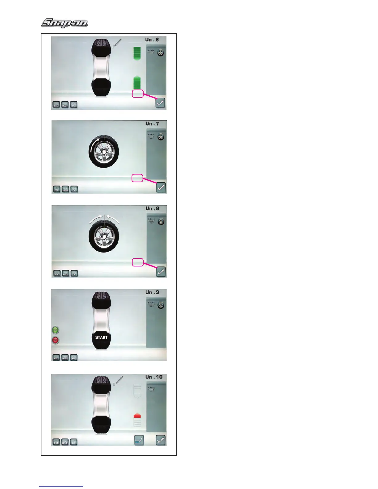
Fig. 5-55 MINIMISATION “Un.6
”
— Rotate the wheel into marking position following
the arrows.
—
In this position mark the tyre, on the outer side of
the wheel, precisely above the main shaft.
— Con! rm by pressing the key 26.
The MINIMISATION “Un.7” screen (Fig. 5-56) is
displayed.
Fig. 5-56 MINIMISATION “Un.7”
— On the tyre changer, turn the tyre relative to the
rim until the valve is aligned with the mark made
on the tyre.
— Con! rm by pressing the key 26.
The MINIMISATION “Un.8” screen (Fig. 5-57) is
displayed.
Fig. 5-57 MINIMISATION “Un.8”
— Clamp the wheel on the balancer.
— Rotate the wheel such that the valve is exactly
perpendicular to and above the main shaft.
—
Enter the valve position by pressing
the
key
26
.
The MINIMISATION “Un.9” screen (Fig. 5-58) is
displayed.
Fig. 5-58 MINIMISATION “Un.9”
START
is signalled on the screen.
— Spinn the wheel.
A measuring run is performed.
The screen MINIMISATION “Un.10”, outside (Fig.
5-59) or the screen MINIMISATION “Un.10”, inside
(Fig. 5-61) is displayed.
Reading H 0
Optimum condition has been achieved and cannot be
improved.
— Continue as shown on screen BALANCING
(Fig. 5-51).


 To Next Page