The document provides operating instructions for the Snap-on MIG135 wire welding machine, covering its installation, description, welding procedures, maintenance, and safety precautions.
Function Description
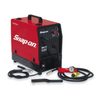
The MIG135 is a wire welding machine designed for welding soft steel, stainless steel, and aluminum. It operates by feeding a continuous wire electrode into the weld pool, creating a strong and durable joint. The machine can be used with or without shielding gas, depending on the type of wire and material being welded.
Usage Features
Installation and Placement:
The machine must be placed in an adequately ventilated, dust-free area, ensuring at least 20 inches of free space around it to prevent overheating. Air intake and outlet cooling slots should not be blocked. The machine is intended for welding purposes only and should not be used to defrost pipes.
Controls and Indicators:
- Switch (A): Turns the machine on and off and regulates the welding voltage range.
- Setting Knob (B): Adjusts the welding wire speed.
- Ground Cable (C): Connects to the workpiece to complete the welding circuit.
- Yellow LED (D): Illuminates when the thermostat is tripped, indicating an interruption in machine operation due to overheating.
- Green LED (E): Indicates that the machine is turned on.
- Welding Torch (F): The primary tool for directing the welding wire and creating the arc.
- Handle (G): Used to lift and transport the machine.
Welding Procedures:
- General Welding: The machine supports both gas-shielded and gasless welding. For gas-shielded welding, a gas cylinder with a pressure regulator and gauge is required. The gas hose connects from the back of the machine to the regulator.
- Mild Steel Welding:
- With shielding gas: Use 75% ARGON + 25% CO2 or 100% CO2. Connect cables as instructed on the internal plate. Select the welding current with the rotary switch and adjust wire speed with the potentiometer until a constant, continuous welding noise is achieved.
- Without shielding gas: Use .035 flux-cored wire (AWS AS.20 E71 TII or E71 TGS compliant). Connect the ground cable clamp to the workpiece. For compact, well-protected welds, work from left to right and top to bottom.
- Aluminum Welding: Requires 100% ARGON shielding gas and a wire composition suited to the base material (e.g., 3-5% silicon wire for ALLUMAN, 3-5% silicon wire for ANTICORODAL, 5% magnesium wire for PERALUMAN, 5% magnesium wire for ERGAL). Use grinding wheels and brushes specifically designed for aluminum to maintain cleanliness. Wire reels should be stored in nylon bags with dehumidifying packets.
- Stainless Steel Welding: Requires a stainless steel wire reel compatible with the material's composition and a gas cylinder containing 98% ARGON + 2% O2.
Wire Loading and Torch Preparation:
Ensure the wire diameter matches the roller. Mount the wire reel and thread the wire through the groove in the small roller. Before pressing the torch trigger, unscrew the contact tip, screw it back on with the correct hole diameter, and slide the tapered gas welding tip on by turning clockwise. Never aim the torch at body parts or other people when loading wire.
Safety Precautions:
The manual emphasizes numerous safety precautions:
- General Safety: Read and understand the manual, paying special attention to safety rules. Contact the dealer if any instructions are unclear.
- Electrical Safety: Electrical shock can be fatal. Do not remove or bypass the grounding prong. Insulate yourself from the workpiece and ground. Wear insulated gloves and clothing. Do not work in humid or wet areas. Disconnect power before maintenance.
- Burns: Wear protective clothing, gloves, helmet with safety goggles, and safety-toe shoes. Avoid oil or greasy clothing. Do not handle hot metal without gloves.
- Fumes: Welding produces harmful fumes and metal dust. Work in a well-ventilated area, keep your head out of fumes, and use exhaust fans or breathing apparatus if necessary. Avoid welding plated metals or those containing lead, graphite, cadmium, zinc, chrome, mercury, or beryllium.
- Fire: Sparks, slag, and hot metal can cause fires. Keep suitable fire-fighting equipment nearby. Remove flammable materials from the welding area (32 ft minimum). Do not weld containers of combustible materials.
- Explosions: Do not weld near containers under pressure or in environments with explosive dusts, gases, or vapors. Handle gas cylinders carefully, ensuring they are secured and not damaged. Never lubricate cylinder valves with oil or grease.
- Radiations: Ultraviolet radiation from the arc can damage eyes and skin. Wear proper clothing and a helmet with appropriate shade lenses (DIN 10 or DIN 11). Protect bystanders.
- Puncture Wounds: Welding wire can cause puncture wounds. Do not press the gun trigger until instructed, and do not point the gun at body parts or other people when threading wire.
- Moving Parts: Moving parts (e.g., fans) can cause injuries. Keep guards and covers securely in place. Only qualified personnel should remove guards for maintenance.
Maintenance Features
General Maintenance:
- Always turn off and unplug the welder before any checking or maintenance.
- Allow the unit to cool before servicing, as surfaces can be glowing hot.
- Periodically remove dust and foreign matter from the transformer or diodes using a jet of clean, dry air.
- Ensure the wire roller groove is aligned with the wire and matches its diameter.
- Keep the gas nozzle interior clean to prevent metal bridges.
- Check the contact tip for excessive expansion and replace if necessary.
- Avoid striking the torch or subjecting it to violent impact.
Troubleshooting Guide:
The manual includes a troubleshooting guide for common issues:
- Limited Current: Check for blown line fuses, burnt diodes or electronic board, or loose connections.
- Metal Spatter: Check for loose contact in the voltage adjustment switch or improper welding parameter settings.
- Wire Jams/Entanglements: Check for wrong contact tip diameter, misalignment of the drive roll groove, or obstructed liner.
- No/Irregular Wire Feed: Check for a drive roll with too large a groove, obstructed liner, loose wire holding roller, or clogged contact tip.
- Porosity in Welding Seam: Check for insufficient shielding gas, excess oxidation of edges, or clogged gas nozzle.
Parts and Consumables:
A detailed list of parts and consumables is provided, including contact tips of various diameters, steel and Teflon liners, and different nozzle types. All consumables and repair parts should be ordered through a Snap-on dealer.