24
www.snapperpro.com
Servicing the Hydraulic System
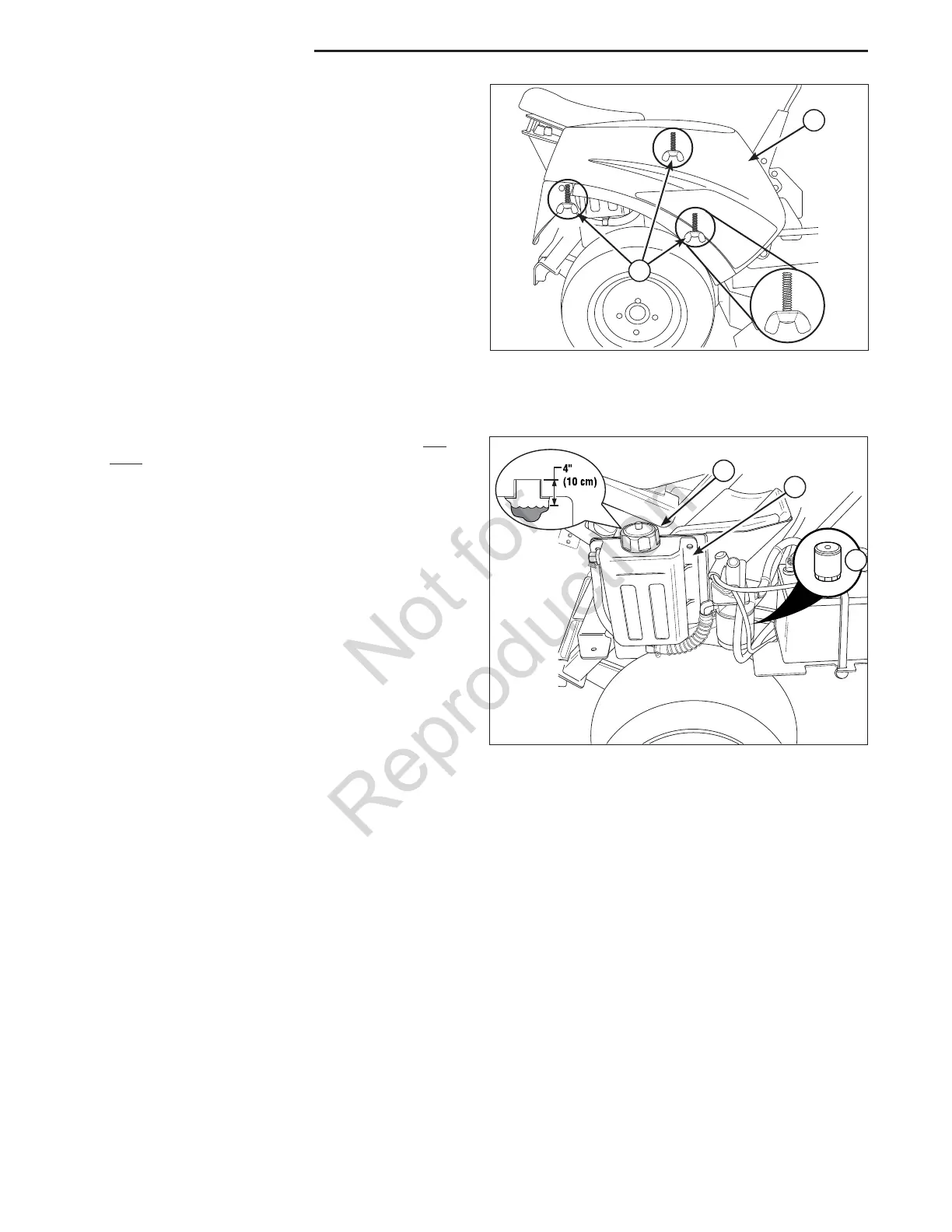
Removing the Tank
The right hand tank (A, Figure 14) must be removed
prior to checking and/or changing the hydraulic oil.
1. Unscrew the three (3) wing bolts (B) that secure
the tank to the unit.
2. Remove the tank from the unit.
Check Hydraulic Oil
1. Before removing the reservoir cap, make sure the
area around the reservoir cap and fill neck of the
reservoir is free of dust, dirt, or other debris.
2. Unscrew the reservoir cap (A, Figure 15).
3. Look down the filler neck of the hydraulic oil
reservoir (B) and observe the oil level. When
cold, the oil level should be approximately 4” (10
cm) below top of the filler neck.
4. If necessary, add SAE 20W-50 motor oil oil. DO
NOT use conventional oils.
5. Reinstall the reservoir cap.
Change the Hydraulic Oil Filter
Change Interval: Every 250 Hours
Filter Part Number: 1719168
NOTE: Removing the oil filter from the filter base
will drain the oil reservoir. Have a suitable container
ready to catch any spilled oil. It is recommended that
this be a dealer-only service item.
1. Locate the transmission oil filter (C).
2. Lubricate the new filter base with a few drops of
transmission oil. Fill the filter half full of oil.
3. Clean the area around the filter base and remove
the filter. Do NOT drain the hydraulic system oil.
4. Thread the new filter onto the filter base until the
gasket makes contact, then tighten 3/4 of a turn
more.
5. Run the unit for several minutes and check the
transmission oil level.
IMPORTANT NOTE: Use caution after changing
the filter; air in the hydraulic system may affect the
responsiveness of the control levers. Repeat step 5
until the air is out of the system.
Reinstalling the Tank
1. Position the tank back on the unit.
2. Secure the tank to the unit using the three (3)
wing bolts.
Regular Maintenance
Figure 14. Removing the Tank
A. Tank
B. Wing Bolts
Figure 15. Servicing the Hydraulic System
A. Reservoir Cap
B. Reservoir
C. Transmission Oil Filter
C
A
B
A
B