14
www.SnapperPro.com
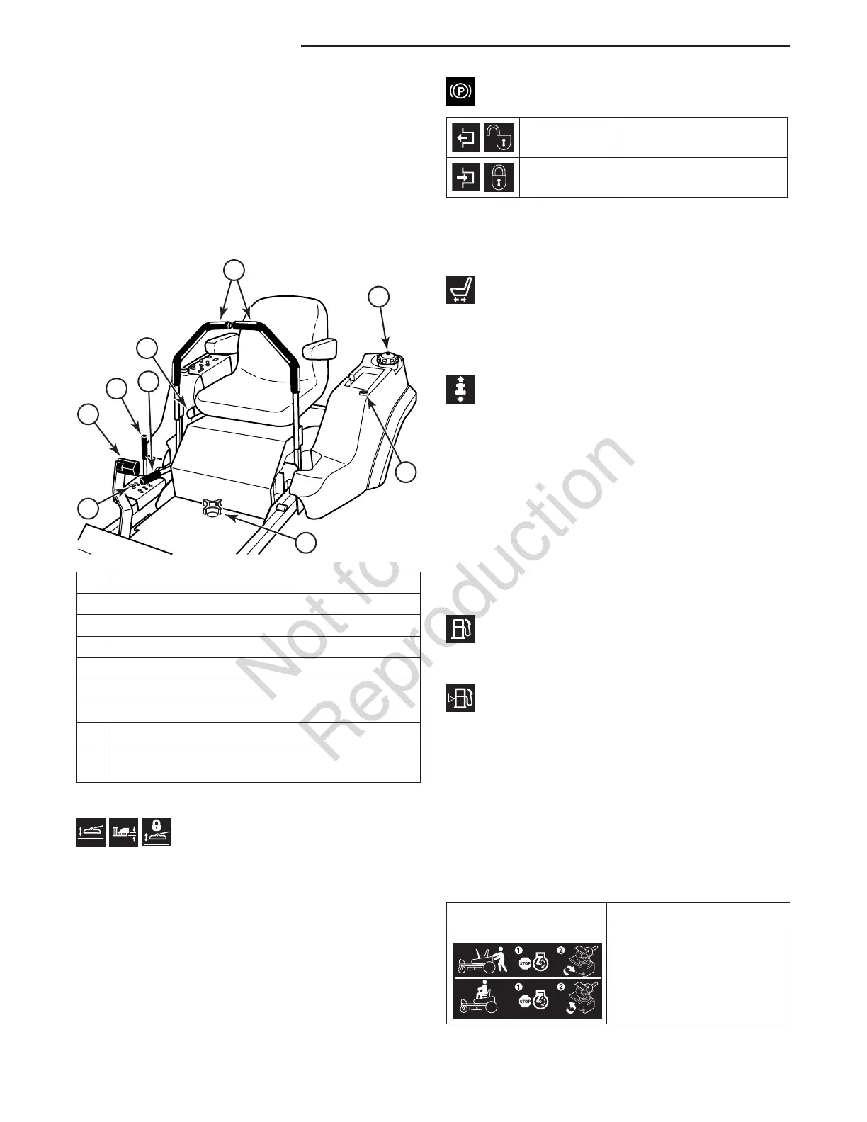
Features & Controls
Deck Lift Pedal, Cutting Height
Adjustment Pin, & Deck Lift Lock Lever
These control the cutting height of the mower deck.
Depress the pedal until it locks into the 6” (15,2 cm)
position. Place the adjustment pin in the desired
cutting height and release the lift lock lever.
Zero-Turn Rider Controls
Control Functions and Locations
The information below briefly describes the function
of individual controls. Starting, stopping, driving,
and mowing require the combined use of several
controls applied in specific sequences. To learn what
combination and sequence of controls to use for
various tasks see the OPERATION section.
A Deck Lift Pedal
B Cutting Height Adjustment Pin
C Deck Lift Lock Lever
D Parking Brake Lever
E Seat Adjustment Lever
F Ground Speed Control Levers
G Fuel Tank Cap
H Fuel Level Gauge
I Removable Floor Pan (S/N: 2016518420 &
Above)
B
A
C
D
E
G
H
F
I
Parking Brake Lever
DISENGAGE Releases the parking
brake.
ENGAGE Locks the parking brake.
Pull the parking brake lever back to engage the parking
brake. Move the lever fully forward to disengage the
parking brake. NOTE: To start the unit the parking
brake must be engaged.
Seat Adjustment Lever
The seat can be adjusted forward and back. Move the
lever towards the left, position the seat as desired, and
release the lever to lock the seat in position.
Ground Speed Control Levers
These levers control the ground speed of the rider. The
left lever controls the left rear drive wheel and the right
lever controls the right rear drive wheel.
Moving a lever forward increases the FORWARD
speed of the associated wheel, and pulling back on a
lever increases the REVERSE speed.
Note: The further a lever is moved away from the
neutral position the faster the drive wheel will turn.
See the Operation section for proper steering
instructions.
Fuel Tank Cap
To remove the cap, turn counter-clockwise.
Fuel Level Gauge
Displays the fuel level in the tank.
Removable Floor Plate
The floor plate can be removed for easy access to
the mower deck. To remove the plate, remove the
retainer hardware and tilt the floor pan up and then
remove from the machine. Reverse the process for
re-installation.
Hydraulic Actuator
Icon Control Name
Hydraulic Actuator
Each transmission on this unit is equipped with a