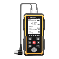
This document describes the SNDWAY SW-6510S Ultrasonic Thickness Gauge, an intelligent device designed for precise thickness measurement of various materials.
Function Description
The SW-6510S is an intelligent ultrasonic thickness gauge that utilizes the latest high-performance, low-power microprocessor technology. Its core principle is ultrasonic measurement, where an ultrasonic pulse generated by the probe passes through a couplant to the measured object. A portion of the ultrasonic signal is reflected by the object's bottom surface, and the probe receives this echo. The device then accurately calculates the ultrasonic wave's round-trip time and, using a specific formula (H = (v × t) / 2, where H is thickness, v is sound speed, and t is propagation time), determines and displays the thickness value.
This instrument is capable of measuring the thickness of metals and other materials, as well as their sound speed. It is particularly useful for monitoring the thinning degree of various pipes and pressure vessels in production equipment due to corrosion. It can also accurately measure various plates and processed parts. Its applications span a wide range of fields, including petroleum, chemical industry, metallurgy, shipbuilding, aviation, aerospace, and others.
The device offers several measurement modes:
- Single Measurement: Provides a one-time thickness reading of the tested area.
- Continuous Measurement: Continuously displays current, maximum, minimum, and average thickness values as the probe moves along the workpiece surface.
- Alarm Measurement: Allows users to set a standard thickness value and tolerance limits. If the measured thickness falls outside these limits, the instrument will issue a continuous "Beep beep beep" alarm.
- Sound Velocity Measurement: Determines the sound speed of a material, particularly useful when the material's sound speed is unknown. This involves measuring the workpiece thickness with a caliper, then adjusting the instrument's thickness value to match, and finally pressing ENTER/REC to calculate the sound speed.
- Calibration: Essential for ensuring accuracy, especially when the probe is replaced, ambient temperature changes significantly, or measurements deviate. Calibration uses a provided thickness block (typically 4mm steel) and sets the material to steel with a sound speed of 5920 m/s (0.233 in/us).
The instrument also includes a storage function, capable of saving up to 300 sets of records. Each record contains the current measurement value, maximum value, minimum value, average value, and material sound velocity. These records can be browsed, deleted individually, or all at once.
Important Technical Specifications
- Display: 2.4-inch black and white dot matrix screen.
- Language: Chinese / English.
- Measuring Range: 1.00~300.00mm (for steel).
- Sound Velocity Range: 1000~9999 m/s.
- Unit: 0.1mm / 0.01mm / 0.01in (selectable).
- Accuracy:
- H < 10mm: ±0.1mm
- H ≥ 10mm: ±(1%H + 0.1)mm (where H is the object's thickness).
- Lower Limit of Pipe Measurement: Φ20*3mm (steel).
- Storage Capacity: 300 sets of data (each set includes material, sound velocity, unit, measurement value, MAX, MIN, and AVG values).
- Battery: Built-in 3.7V 2000mAh Li-ion battery.
- Charging Specification: DC5V 1A Type-C interface.
- Battery Life (fully charged): Approximately 16 hours.
- Working Temperature & Humidity: 0°C~40°C, 10%RH~80%RH.
- Storage Temperature & Humidity: -10°C~+50°C, 10%RH~70%RH.
- Dimension: 140x66x28.5mm.
Material Sound Velocity Reference (Appendix A): The manual provides a comprehensive list of materials and their approximate sound velocities (in/µs and m/s), including steel, stainless steel, brass, copper, iron, cast iron, lead, nylon, silver, gold, zinc, titanium, tin, acrylic resin, epoxy resin, ice, nickel, plexiglass, porcelain, PVC, quartz glass, and vulcanized rubber. The instrument also supports three user-defined custom materials.
Usage Features
-
Intuitive Interface: The main display shows coupling state, measurement mode, unit system, battery power, alarm sound switch, and detailed information including thickness value, material, sound speed, maximum, minimum, and average readings.
-
Easy Operation:
- Power On/Off: Short press the power key to turn on; long press to turn off.
- Automatic Shutdown: The instrument automatically shuts down after 5 minutes of inactivity (adjustable). A forced shutdown can be performed by long-pressing the power button for more than 10 seconds.
- Couplant Application: Apply couplant evenly to the tested area for tight coupling between the probe and the material. The coupling mark on the screen indicates proper coupling.
- Menu Navigation: Long press MODE/MENU to access the main menu, which includes material selection, sound speed adjustment, unit settings, record operations, system settings, "About" information, and factory reset. Up/Down arrows navigate options, and ENTER/REC selects.
- Material Selection: Users can choose from predefined materials or custom materials.
- Sound Speed Adjustment: Allows fine-tuning of sound speed for custom materials within a range of ±200m/s (or ±250mm for custom materials in reverse measurement mode).
- Unit Settings: Switch between mm and in.
- Record Management: Browse records by first page, last page, or selected group. Records can be deleted individually or all at once.
- System Settings: Adjust sound on/off, backlight time, automatic shutdown time, alarm settings, and language (Chinese/English).
- Alarm Settings: Configure standard thickness values and tolerance limits for alarm functionality.
- Factory Reset: Restore the instrument to its default factory settings.
-
Measurement Considerations (Appendix B):
- Surface Condition: Requires removal of dust, dirt, rust, and paint. Rough surfaces need to be smoothed (grinding, filing) and may require high-viscosity couplants. Fine grooves should be measured with the probe's crosstalk spacer plate perpendicular or parallel to the grooves.
- Cylindrical Surfaces: For pipes, the probe's crosstalk barrier plate should be positioned perpendicular to the axis for larger diameters, or both parallel and perpendicular for smaller diameters, taking the minimum reading.
- Composite Shapes: For shapes like pipe elbows, a second measurement with the probe's crosstalk barrier plate perpendicular and parallel to the axis is recommended, taking the smaller value.
- Non-parallel Surfaces: The other surface of the measured material must be parallel or coaxial with the measured surface for stable and reliable readings.
- Temperature Influence: Material thickness and ultrasonic wave speed are affected by temperature. For high accuracy, use a test block of the same material and approximate thickness under similar temperature conditions to obtain a temperature compensation coefficient.
- Material Attenuation: Materials like fibers, porous, or coarse crystals can cause significant scattering and energy attenuation, leading to abnormal or no readings. This gauge may not be suitable for such materials.
- Reference Blocks: Using reference blocks of the same material and similar thickness as the tested object improves accuracy. For thin materials, a test block helps determine the exact lower limit. For thick materials or alloys with complex internal structures, a test block close to the material is recommended for calibration.
- Casting Measurements: Coarse grains and insufficient density in castings can cause sound energy attenuation and abnormal reflections. Higher viscosity couplants are recommended for rough casting surfaces. Calibrate with a test block of the same material and measurement direction.
- Ultra-thin Materials: Measuring below the probe's lower limit can cause errors like "double refraction" (displayed reading is twice the actual thickness) or "pulse envelope, cyclic Jump" (measured value greater than actual thickness). Repeat measurements for critical thin materials.
- Rust Spots/Corrosion Pits: These can cause irregular or no readings. Exercise caution and test at different angles.
- Material Identification Errors: Calibrating with one material and measuring another will lead to errors. Select the correct sound speed.
- Oxide Layer: A dense oxide layer on metals (e.g., aluminum) can cause measurement errors due to different sound propagation speeds. Calibrate with a sample block from the same batch.
- Abnormal Readings: Rust spots, corrosion pits, and internal defects can cause abnormal readings.
- Couplant Selection: Use appropriate couplant type and amount. Low viscosity for smooth surfaces, high viscosity for rough, vertical, or top surfaces.
Maintenance Features
- Battery Maintenance: Fully charge the product before long-term storage and recharge every six months to prevent battery damage. The built-in lithium battery is not removable.
- Probe Care:
- Avoid strong vibration.
- When inserting/unplugging, hold the movable jacket and apply force along the axis; do not rotate to prevent damage to the cable core.
- Wipe off any residual couplant after use to prolong probe life.
- Avoid oily environments; if unavoidable, minimize contact time and dry the probe surface with oil-absorbing paper afterward.
- If the probe is worn, leading to unstable values, it should be replaced. Minor wear can be polished with fine sandpaper or oilstone to restore smoothness and parallelism.
- Calibration Block Care:
- Clean the calibration block after use.
- Avoid getting it sweaty in high temperatures.
- For long-term storage, apply a little grease to prevent rust; wipe off grease before reuse.
- Case Cleaning: Wipe gently with a damp cloth. Avoid alcohol or diluents, especially on the window, as they can be corrosive.
- Troubleshooting & Repair: If abnormal phenomena occur (damage, abnormal display, large error, keyboard malfunction), do not disassemble or adjust fixed parts. Contact local distributor or manufacturer for service and warranty.