EasyManua.ls Logo

SNIPER V2 Inox - User Manual

SNIPER V2 Inox
2 pages
Print Icon
To Next Page IconTo Next Page
Loading...
Warning: Laser Radiation
www.sniper.com.au OWNERS GUIDE - Model V2 Inox US Patent 6, 772 524
Make sure the Spindles and Magnetic Vee Block are clean and free of debris before attaching the Snipers.
Fit your Snipers by carefully placing them onto the spindles with the forward arrows facing the front of the kart.
These units will fit any diameter up to 63mm (2 1/2 inch), for non magnetic spindles simply use a cable tie or
similar to attach the units.
The simplest way to get the steering centralized is to place the included steel rule in the centre across the
lower steering shaft bracket and turning the steering shaft until you visually see an equal distance at both
ends of the rule to the tie rods. You may clamp the top steering bush with vice grips or similar, if desired.
Turn your units on and align them to each other by centering the spirit levels, the spirit levels should be
checked occasionally during aligning the kart.
You are now ready to begin adjustment of toe and camber. The laser dot in the center of the grid is the beam
shining out at the opposing unit. Readings are then taken from the unit opposite to the spindle being adjusted.
REMEMBER: Each line equals 2mm of toe or camber per side. Add both sides readings together for the total
alignment setting
Warranty conditions of the country in which the purchase was done, are valid. Keep proof of purchase. Manufactures Warranty is valid for 24
months from month of manufacture.
Caution– Use of controls or adjustments or performance of procedures other than those specified herein may result in hazardous radiation exposure.
The unit should not be exposed to temperatures in excess of 50 degrees Celsius or left in direct sunlight for extended periods. Damage to the
laser module and spirit level vials may result. To switch on the unit turn the red plastic cap on the back of the unit clockwise until it stops. To turn
the unit off, rotate the cap anti-clockwise one half turn to make sure the cap will not accidentally make contact when not in use.
To replace the battery, turn the cap anti-clockwise until you can remove it from the unit completely. The batteries are CR-1/3N.
No other maintenance is to de done by the user as it may effect the radiation exposure, any other maintenance, service or in the unlikely event that
the units need parts replaced / repaired they must be done by Sniper Precision Technologies.
Do not remove or modify the decals on the units.
This laser product is designated as Class 1 during all procedures of operation.
Wavelength: 650nm, nominal.
Laser Power for Classification: <0.39mW CW.
Beam Diameter: <1.2mm at aperture.
Divergence: <1mRad
Transverse Beam Mode: TEM00
Sniper Precision Technologies V2 Inox
52 Country Drive, Oakford Australia 6121
CLASS1 LASER PRODUCT CLASSIFIED EN/IEC 60825-1 2007
Complies with US FDA performance standards for laser
Products except for deviations pursuant to Laser
Notice No. 50, Dated June, 2007. Manufactured: Month/Year
Question and Answer IconNeed help?

Do you have a question about the SNIPER V2 Inox and is the answer not in the manual?

Summary

Sniper Laser Alignment System Overview

Laser Safety Precautions

Advises on safe usage, avoiding exposure, and temperature limits.

Basic Unit Operation and Maintenance

Instructions for turning the unit on/off, battery replacement, and maintenance.

Initial Setup and Alignment Procedure

Steps for attaching units to spindles and aligning them using spirit levels.

Reading Toe and Camber Measurements

Explains how to interpret laser dots on the grid for toe and camber measurements.

Advanced Alignment Checks

Caster, Chassis Twist, and Spindle Checks

Procedures for measuring caster, checking chassis twist, and spindle straightness.

Dynamic Alignment Setup

Guidance on setting up alignment with the driver in the kart for accurate results.

Wheelbase and King Pin Bolt Checks

Methods to check wheelbase symmetry and king pin bolt straightness.

Sniper Unit Calibration Check

Procedure to verify the accuracy and calibration of the Sniper units.

Operating Principles of the Sniper Unit

Laser Axis and Grid System

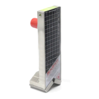
Explains how the unit projects a laser axis onto a grid for measurements.

Measurement Units and Interpretation

Defines grid lines as 2mm for toe/camber and how to calculate total settings.

Overview

The Sniper V2 Inox is a laser-based alignment tool designed for kart racing, enabling precise measurement and adjustment of toe, camber, and caster. It is a Class 1 laser product, ensuring safe operation under normal conditions.

Function Description:

The core function of the Sniper V2 Inox is to re-create the axis through the two front wheels of a kart using laser beams. Each unit is hand-calibrated to project a laser beam perfectly parallel to its attached spindle. This laser beam is then projected onto a visual grid system on the opposing unit, allowing for simultaneous measurement of camber and toe. The device helps users achieve symmetrical front-end geometry by providing clear visual feedback on alignment settings. It also facilitates checking for chassis twist, kingpin straightness, spindle bends, and wheelbase consistency.

Important Technical Specifications:

  • Laser Classification: Class 1 laser product, classified EN/IEC 60825-1 2007. Complies with US FDA performance standards for laser products, except for deviations pursuant to Laser Notice No. 50, Dated June, 2007.
  • Wavelength: 650nm, nominal.
  • Laser Power: <0.39mW CW (Continuous Wave).
  • Beam Diameter: <1.2mm at aperture.
  • Divergence: <1mRad.
  • Transverse Beam Mode: TEM00.
  • Power Source: CR-1/3N batteries.
  • Operating Temperature: Not to exceed 50 degrees Celsius.
  • Measurement Grid: Each horizontal line on the grid represents 2mm of camber per side. Each vertical line represents 2mm of toe per side. A central dot on the grid visually aids in representing 1mm. Therefore, one full grid position movement on the camber plane equates to "4mm camber," and on the toe plane, it equates to "4mm toe."
  • Spindle Compatibility: Fits any diameter up to 63mm (2 1/2 inches).
  • Caster Measurement: 1 degree of castor is approximately 4mm difference on the rule.

Usage Features:

  • Attachment: The Snipers attach to the kart's spindles using magnetic Vee Blocks. For non-magnetic spindles, cable ties or similar methods can be used. The forward arrows on the units should face the front of the kart. Before attachment, ensure spindles and magnetic Vee Blocks are clean and free of debris.
  • Power On/Off: To switch on, turn the red plastic cap on the back of the unit clockwise until it stops. To switch off, rotate the cap anti-clockwise one half turn to prevent accidental contact.
  • Centralizing Steering: A steel rule is placed across the lower steering shaft bracket. The steering shaft is turned until an equal distance is visually observed at both ends of the rule to the tie rods. The top steering bush can be clamped with vice grips if desired.
  • Alignment Adjustment: Once powered on, users align the units by centering the spirit levels. Readings for toe and camber are taken from the unit opposite the spindle being adjusted. Each line on the grid represents 2mm of toe or camber per side. Both sides' readings are added for the total alignment setting. Spirit levels should be checked occasionally during alignment.
  • Dynamic Setting: For the most accurate setup, the kart should have its wheels fitted, be placed on a flat, level surface, and have the driver in the kart. This "dynamic" setting simulates real-world track conditions and accounts for clearances in steering components.
  • Caster Check: After setting toe and camber, caster can be checked. A provided magnet is attached to a steel rule at the center of the kart, towards the front. The steering wheel is turned one way until a laser dot from the Sniper unit crosses the rule, and the distance is recorded. The process is repeated for the other direction. If both laser dots record the same height, caster is equal. A difference over 2mm indicates a potential issue with camber/caster adjusters or chassis.
  • Chassis Twist Check: A spare axle or straight edge is placed on top of the Sniper units. By viewing the gap between the straight edge and the rear axle (with a light background), users can detect twists as small as 2mm. Minor twists can sometimes be eliminated using the clearance in the bolt holes on the rear bearing carriers.
  • Wheelbase Check: After front-end alignment, wheelbase can be checked by measuring from the rear axle to the spindle on each side. Measurements should ideally be the same, with anything under 5mm difference being acceptable.
  • Kingpin Bolt Check: To check if kingpin bolts are straight, loosen the bolt slightly and rotate it. If the camber readings on the opposing Sniper move, the bolt is bent. If there is no effect, the bolt is straight.
  • Spindle Bend Check: Units are placed close to the shoulders of the spindles. Sliding one unit towards the end of the spindle will reveal a bend if toe or camber readings change.
  • Sniper Calibration Check: To verify Sniper calibration, units are fitted as normal, and toe and camber readings are recorded. Then, the units are placed back to front (forward arrows pointing to the back of the kart). The toe and camber readings should be the same as before within 1mm.

Maintenance Features:

  • Battery Replacement: To replace batteries, turn the red cap anti-clockwise until it can be completely removed. The units use CR-1/3N batteries.
  • User Maintenance Limitations: No other maintenance is to be done by the user, as it may affect radiation exposure. Any other maintenance, service, or parts replacement/repair must be performed by Sniper Precision Technologies.
  • Decal Integrity: Users should not remove or modify the decals on the units.
  • Environmental Protection: The unit should not be exposed to temperatures exceeding 50 degrees Celsius or left in direct sunlight for extended periods, as this can damage the laser module and spirit level vials.
  • Warranty: The manufacturer's warranty is valid for 24 months from the month of manufacture. Users should keep proof of purchase. Warranty conditions are specific to the country of purchase.

SNIPER V2 Inox Specifications

General IconGeneral
BrandSNIPER
ModelV2 Inox
CategoryAutomobile Accessories
LanguageEnglish