SECTION 7
DESCRIPTION
T B M
700 PILOT’S INFORMATION MANUAL
Back to
Contents
Page 7.8.9
Rev. 8
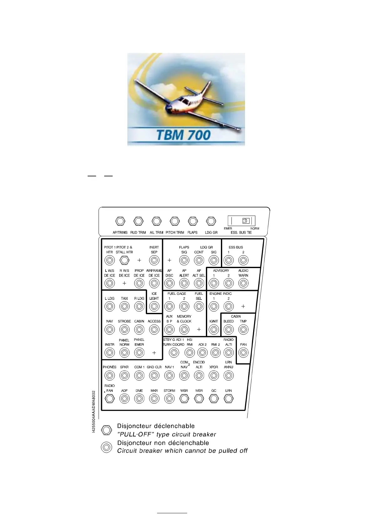
Figure 7.8.3A (2/2) – CIRCUIT BREAKER PANEL (Typical arrangement)
(*) Circuit breaker which cannot be pulled off up to S / N 17
NOTE 1 :
If ADF 2 is installed, its circuit breaker is installed on a free location,
HSI RMI becomes HSI and ADF becomes ADF 1 RMI.
TBM 700A from S/N 11