directly on the meter scale in terms of
megohms.
To make the instrument ready for
insulation resistance
tests proceed as
follows:
1.
Set
the selector switch on position Mxl (See chart
below).
2.
Switch
the meter to the 5 ma. range.
3.
Adjust
the voltage control so that the meter
reads
infinity
)
which is
the null position.
4. Connect the test
leads, with the rubber
protections
over the dips, across the condenser under
examina-
tion and read
the meter deflection, which
is given
directly in megohms.
On
low capacity units
like
mica condensers,
the
reading
can be
taken almost
immediately; on higher capacity units it
will
be
necessary to wait until the condenser becomes
charged
and
the meter deflection
comes to rest;
this
may take about I
minute
for a I mfd. capaci-
tor. The difference in time between
low and high
capacity condensers
is due to the difference in
the
charging
rate. The high capacity
condenser
takes longer to charge.
S«lecfor
Insulation Resistance Multiply
Setting
in Meqohms
Scale by
MX
1 3 to 100
megohms 1
MX 10
30 to 1000 megohms
10
MX 100
300 to 10000
megohms 100
If the meter
deflection is greater
than 100 megohms
on range
MX I, set selector
switch on position MX
10
and, if it is still greater
than 100 on this
range, set the
selector switch
on range MX
100. the next highest setting.
SATISFACTORY —
Insulation values greater
than 50
megohms.
(See note below.]
LEAKY
—
Insulation values
less than 50 megohms.
(Re-
place condenser)
SHORTED OR
LESS THAN
3
MEGOHMS
—
Meter
deflection reads zero.
(Replace condenser.)
OPEN
—
No variation
in the meter deflection. (Replace
condenser.)
The
leakage check
on paper,
mica,
trimmer,
and
all
solid dielectric
condensers is made
in the manner de-
scribed.
NOTE
—
The insulation resistance
of 50 megohms will
be found satisfactory
for most applications
with the
exception
of coupling condensers.
In the case of
coupling condensers
the insulation resistance
should
be above
200 megohms.
Values of resistors greater than 3
megohms
can be
tested on
this range. The checks are made in the man-
ner described above.
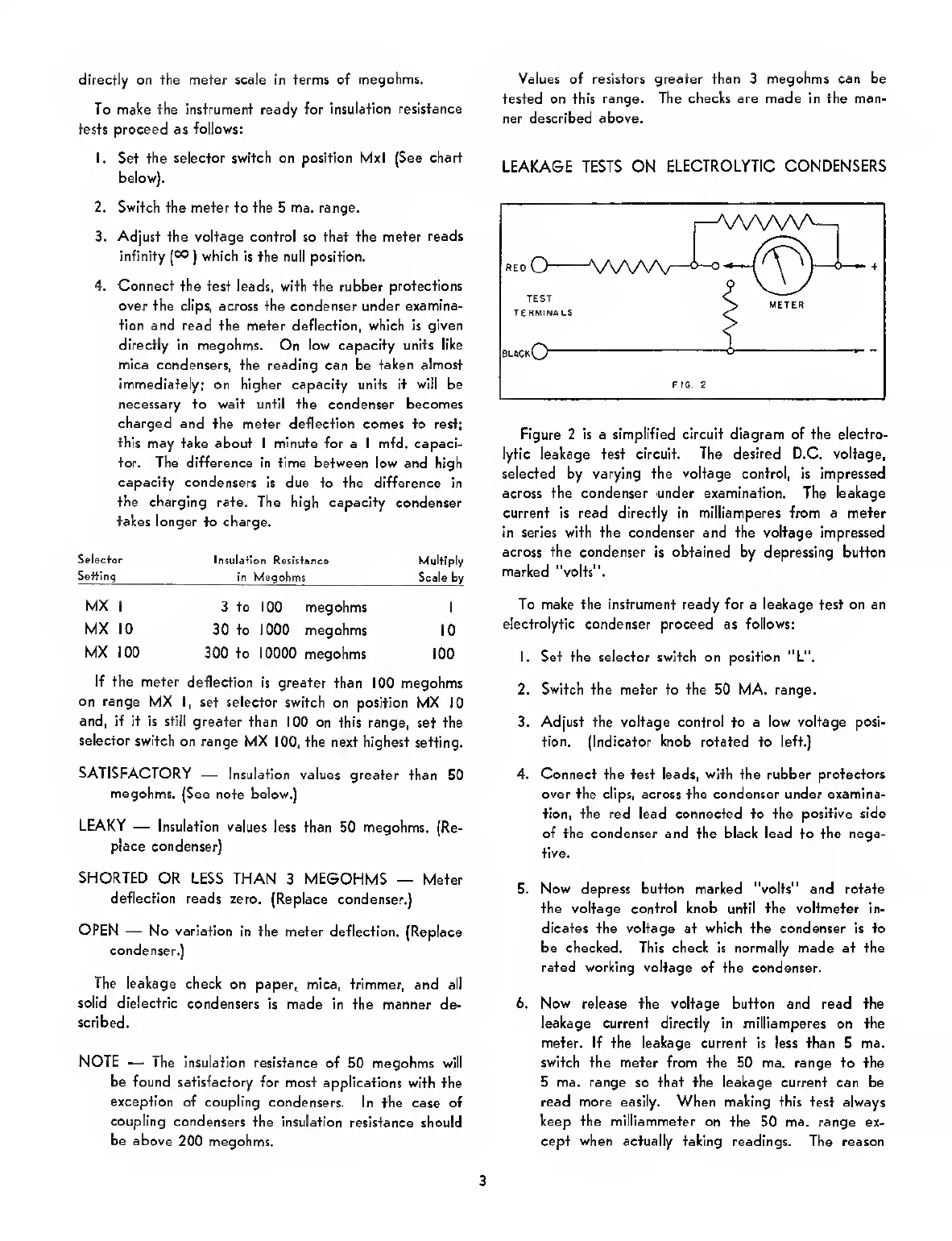
LEAKAGE TESTS ON
ELECTROLYTIC CONDENSERS
Figure 2 is a simplified circuit diagram of the electro-
lytic leakage test
circuit. The desired
D.C.
voltage,
selected by varying the voltage control, is impressed
across the condenser under examination. The leakage
current is read directly in milllamperes from a meter
in series with the condenser and the voltage impressed
across the condenser is obtained
by depressing button
marked
"volts".
To make the instrument ready for a leakage test on an
electrolytic
condenser proceed as
follows:
1. Set the selector switch on position ”L",
2. Switch the meter to the 50 MA. range.
3. Adjust the voltage control
to
a low voltage posi-
tion. (Indicator knob
rotated to
left.)
4. Connect the test leads, with the rubber
protectors
over the clips, across the condenser under examina-
tion, the red lead connected to the
positive side
of the condenser and the black lead
to
the nega-
tive.
5. Now depress button marked "volts" and rotate
the voltage control knob
until
the voltmeter in-
dicates the voltage at
which
the condenser is to
be checked. This check is normally made at the
rated working voltage
of the condenser.
6. Now release the voltage button and read the
leakage current directly
in
milliamperes
on
the
meter. If
the leakage current is less than 5 ma.
switch the meter from the 50 ma. range to the
5 ma. range
so
that
the
leakage
current can be
read more easily. When making this test always
keep the milliammeter on the
50
ma.
range ex-
cept
when
actually taking readings. The reason
3
 Loading...