for this is that it is impossible to damage the
meter when
it is adjusted for the high current
range because the instrument
has
been designed
to prevent
excess current
from
damaging the meter
element.
SATISFACTORY
—
The leakage current should come
down
to 5
ma.
or less. The time required for
the
current to be reduced to this value depends upon
the length of time the capacitor
has been out of
service.
HIGH LEAKAGE
—
A condenser in which the leakage
current does not come down
to 5 ma.
after 20
to
30 minutes of
application of rated D.C. voltage
should be considered defective and replaced.
SHORTED
—
Appreciable flickering in the leakage cur>
rent. (Replace
condenser.)
Tests of electrolytic
condensers that have been out
of
service
for long periods of time may be speeded
up
by continued adjustment
of the
voltage
so that it Is kept
at
the initial setting of the test voltage.
For
example as the leakage current is reduced the
D.C. test voltage will have
a tendency to
Increase
re-
sulting in an increase in the leakage current. Reducing
the test voltage
to the rated value will reduce the leak-
age current proportional to the reduction
in
voltage.
It sometimes happens when
the condenser has been
out of service
15 to 20 months that it Is more convenient
to start with a D.C. voltage less than rating not
sufficient
to give 40
to
50 milliamperes
and to increase the voltage
as the
current is decreased up to rated voltages. When
rated voltage is reached
proceed as described above.
CAPACITY
OF PAPER, MICA, TRIMMER,
ELECTROLYTIC AND
AIR CONDENSERS
POWER FACTOR
OF ELECTROLYTICS
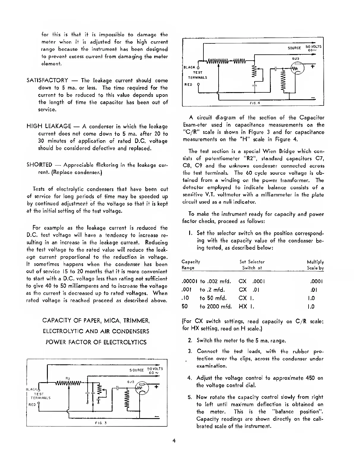
A circuit diagram of the section of the Capacitor
Exam-eter used in capacitance measurements
on
the
"C/R" scale is
shown
in Figure 3 and for capacitance
measurements on the "H" scale in Figure 4.
The test section Is a special Wien Bridge which con-
sists of potentiometer "R2", standard capacitors C7,
C8,
C9 and the
unknown
condenser connected across
the test terminals. The 60 cycle source voltage is ob-
tained from a winding
on
the power transformer.
The
detector
employed to indicate balance consists of a
sensitive V.T.
voltmeter with a milliammeter in the plate
circuit used
as
a null Indicator.
To make the
instrument ready for capacity and power
factor checks, proceed as follows:
I. Set the selector switch on the position correspond-
ing
with
the capacity value of the condenser
be-
ing tested, as described below:
Capacity Set Selector
Multiply
Switch
4t Sc^le by
.00001 to .002 mtd. CX .000
1
.0001
.001 to .2 mfd. CX
.01 .01
.10
to 50 mfd. CX 1. 1.0
50 to 2000 mfd. HX 1.
1.0
(For CX switch settings,
read capacity on C/R scale;
for HX
setting, read on H scale.)
2.
Switch
the meter to the
5
ma. range.
3. Connect the test leads, with the rubber pro-
tection over the clips,
across the condenser under
examination.
4. Adjust the voltage control to approximate 450 on
the voltage control
dial.
5.
Now
rotate the capacity
control slowly from right
to left until maximum deflection Is obtained on
the meter.
This Is the "balance position".
Capacity readings are shown directly on the cali-
brated scale
of
the
Instrument.
4
 Loading...