For eleclrolyflc condensers, balance fhe capadfy con-
trol
as
described above, and then adjust the Power Fac-
tor Control for the maximum
meter
deflection.** Then
read the power factor directly from the
scale.
In this
check
the voltage control setting is not critical at all and
may be adjusted to any desired value
to
give
a
readable
deflection
of the meter.
If adjusted
for a high
deflection
the
instrument is
more sensitive than when adjusted for
a low
deflection.
**Note: It is often desirable
to rebalance
the capa-
citor control after the power factor
adjustment
has been made.
OFF CAPACITY
—
Condensers which measure more
than
30%
lower than rated
capacity should
be re-
placed by units of the correct value. For bypass
and filter use no limit
need generally be placed on
the
upper
capacity
limit. Special cases will be con-
sidered later.
The capacity of A.C. motor starting electrolytic
condensers should be within
±20%
of rated value
for satisfactory operation.
However,
a slightly
greater tolerance is permissible in some cases.
OPENS
—
Any condensers which can
be
balanced
only
at "open" on the capacity scale, after careful ad-
justments have been made
with
the selector switch
In
positions CX
.0001, CX .01,
CX I,
and
HX
I,
are
open and should be replaced.
INTERMITTENTS
—
An intermittent will be indicated by
a noticeable flickering of the meter needle. Re-
place condenser.
HIGH POWER FACTOR
—
Any condenser
for which
a balance Is not obtained on any position of the
power
factor control should be replaced. For A.C.
and motor starting electrolytic condensers, power
factors above
20%
generally
are
unsatisfactory.
Such condensers should be replaced.
SHORTED
—
Shorted condensers will balance on the
"short" position of the capacity
control for any
setting
of the selector switch if shorted solidly.
There will be no balance obtained
if the short is
high
resistance. Shorted condensers
will show up
on the leakage
test as well.
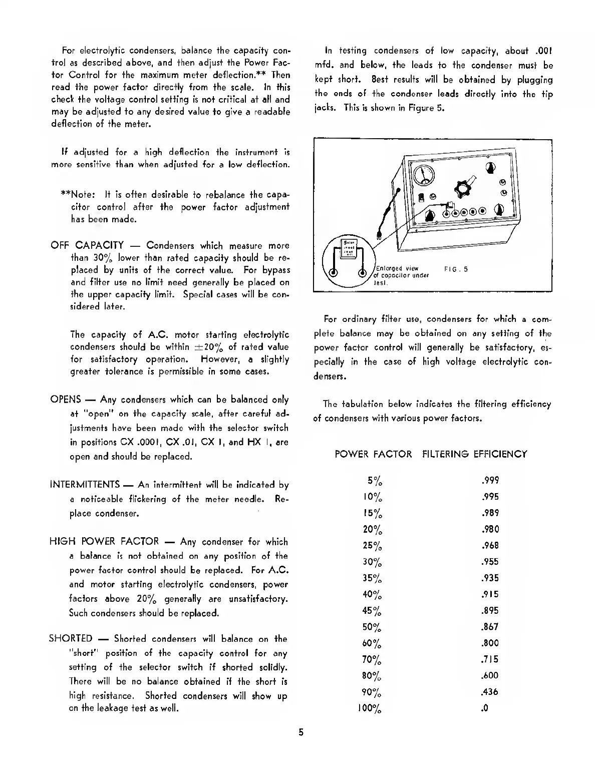
In testing condensers of low capacity,
about .001
mfd.
and
below,
the leads to the
condenser must be
kept short.
Best results will be obtained
by plugging
the ends
of the condenser leads directly
Into the tip
jacks.
This
is
shown in Figure
5.
For ordinary filter use, condensers for which a
com-
plete balance may be
obtained
on any setting of the
power factor control will generally be satisfactory,
es-
pecially in the case
of high voltage
electrolytic con-
densers.
The tabulation below indicates the
filtering
efficiency
of condensers
with various power factors.
POWER
FACTOR FILTERING EFFICIENCY
5%
.999
10%
.995
15%
.989
20%
.980
25%
.968
30%
.955
35%
.935
40%
.915
45%
.895
50%
.867
50%
.800
70%
.715
80%
.600
90%
.436
100%
.0
5
 Loading...