POWER FACTOR
CORRECTION FOR LINE
FREQUENCY
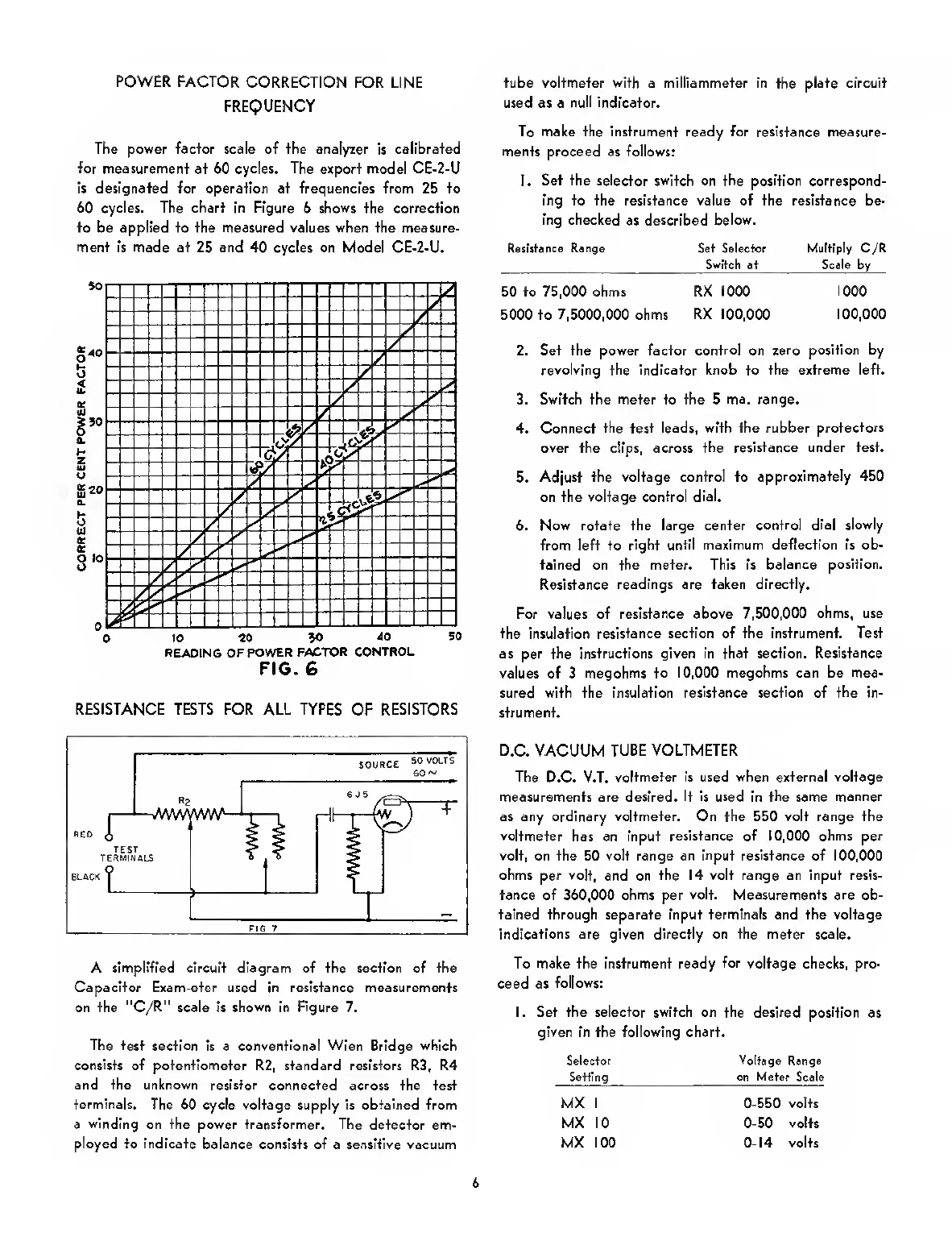
The power facfor scale of fhe analyzer is calibrated
for measurement
at 60
cycles. The
export model CE-2-U
Is designated for operation at frequencies from 25 to
60 cycles. The chart in Figure
6
shows
the
correction
to be applied to the measured values when the measure-
ment is made at 25 and
40
cycles on
Model CE-2-U.
0
10 to
90
40
50
READING
OF
POWER
FACTOR CONTROL
FIG. 6
RESISTANCE TESTS FOR ALL TYPES OF RESISTORS
A simplified circuit diagram of the section of the
Capacitor Exam-eter used in resistance measurements
on
the
"C/R" scale is
shown
in
Figure
7.
The test section
Is a
conventional Wien
Bridge which
consists of potentiometer R2, standard resistors R3, R4
and the unknown resistor connected across
the test
terminals. The
60 cycle voltage supply is obtained from
a
winding
on the power transformer. The
detector em-
ployed to indicate balance
consists of a sensitive vacuum
tube voltmeter with a mllliammeter in
the
plate circuit
used as a
null indicator.
To make the instrument ready for resistance measure-
ments proceed as follows:
1.
Set the selector switch
on
the position correspond-
ing to the resistance value of the resistance be-
ing checked
as described
below.
Ratistance
Range
Set
Selector Multiply
C/R
Switch
at Seale by
50 to 75,000 ohms RX 1000
1000
5000 to 7,5000,000 ohms
RX
100,000
100,000
2. Set the power factor
control
on
zero position by
revolving
the
Indicator knob to the extreme left.
3. Switch the meter to the 5 ma.
range.
4. Connect
the
test
leads, with the rubber
protectors
over the clips, across
the resistance under test.
5.
Adjust the voltage control to
approximately 450
on the voltage control
dial.
6. Now rotate the large center
control dial slowly
from left to
right until maximum deflection is ob-
tained on the meter. This is
balance position.
Resistance
readings are taken directly.
For values of resistance above 7,500,000
ohms, use
the
insulation
resistance section of the Instrument. Test
as
per the
instructions given in that section.
Resistance
values of 3
megohms to 10,000 megohms can be mea-
sured with the insulation
resistance
section of
the
In-
strument.
D.C.
VACUUM
TUBE VOLTMETER
The
D.C. V.T.
voltmeter Is used when external voltage
measurements are desired.
It is used
in
the
same
manner
as any ordinary voltmeter. On the 550 volt range the
voltmeter
has an input
resistance of 10,000 ohms per
volt, on the 50 volt range an
Input resistance
of 100,000
ohms per volt,
and on
the 14 volt range an input resis-
tance of 360,000 ohms per
volt. Measurements are
ob-
tained through separate Input terminals and the voltage
indications are given directly on the meter scale.
To make the instrument ready
for
voltage checks, pro-
ceed as
follows:
I. Set the selector switch on the desired position
as
given in the following chart.
S«lecfor Voltage
Range
Setting
on Meter
Scale
MX I
0-550
volts
MX 10
0-50
volts
MX 100
0-14
volts
6
 Loading...