a
C.
2. Insert the test leads, with the rubber
protectors
over the clips,
into the tip jacks marked "D.C.
volts". The red plug should be connected
to the
red jack and the
black plug to black jack
to ob-
tain the correct polarity.
3.
Switch the meter
to the 5 milliampere range.
4. Adjust the voltage control
so that the
meter reads
"O" on scale V.D.C. This is
the
null point.
5. Now
connect the test leads across the voltage to
be measured
and read the
meter detlection which
is
given directly in volts.
A.C.
VACUUM TUBE VOLTMETER
The A.C. V.T. voltmeter is used as an output indicator
for circuit alignment.
The
voltmeter has an input re-
sistance
of 10 megohms and has a range of 10 to 50
volts
D.C. To make the instrument ready for voltage
checks,
proceed as follows;
1. Set the selector switch on position MX 100.
2. Insert
the test
leads, with
the rubber protectors
over the clips, into the tip jacks marked "A.C.
volts".
3.
Switch
the meter to the 5 ma. range.
4. Adjust
the
voltage
control so that the meter reads
5 ma. This is the null point.
5. Now
connect the test leads across the voltage to
be measured and read
the
meter
deflection which
Is given
in milliamperes.
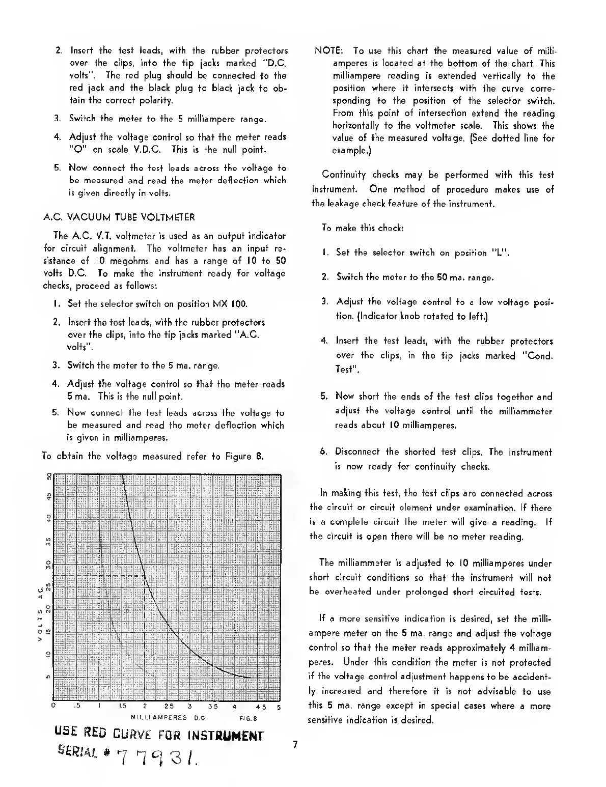
To obtain the voltage
measured refer to Figure 8.
MILL! AMPERES
O.C.
FIG
8
USE
RED
CURVE
FOR
INSTRUMENF
NOTE: To use this chart the measured value of
mill!-
amperes is located at the bottom
of the chart. This
milliampere
reading is extended vertically to the
position where it intersects with
the curve corre-
sponding
to the
position
of the selector switch.
From this point of intersection extend
the reading
horizontally
to the
voltmeter
scale. This shows
the
value of the measured voltage. (See dotted
line for
example.]
Continuity checks
may be performed
with
this test
instrument. One method of procedure makes
use of
the leakage check feature
of the instrument.
To
make this check:
1.
Set the selector switch on
position "L".
2. Switch the meter to the
50 ma. range.
3. Adjust the voltage
control to
a
low voltage
posi-
tion. (Indicator knob rotated
to left.}
4. Insert the
test leads, with the rubber protectors
over the clips, in
the tip jacks marked "Cond.
Test".
5.
Now
short the ends
of the test clips together and
adjust the voltage
control until the
mlltiammeter
reads about 10 milliamperes.
6. Disconnect the
shorted test clips. The instrument
is now ready for
continuity checks.
In making
this test, the test clips
are connected across
the circuit or circuit
element under examination.
If there
is a complete circuit the meter will give
a reading. If
the circuit is
open there
will
be no meter
reading.
The milliammoter
is adjusted
to 10
milliamperes
under
short circuit
conditions so that the instrument will
not
be overheated
under prolonged
short circuited tests.
If
a more sensitive indication
is
desired,
set the milli-
ampere
meter on the 5 ma. range and adjust the
voltage
control so that
the
meter
reads approximately 4 milliam-
peres. Under this condition the meter
Is not protected
If the voltage control adjustment
happens to
be accident-
ly Increased and therefore
It Is not advisable
to use
this
5 ma. range except in special cases where
a more
sensitive
Indication Is desired.
7
 Loading...