320102037108
Commissioning
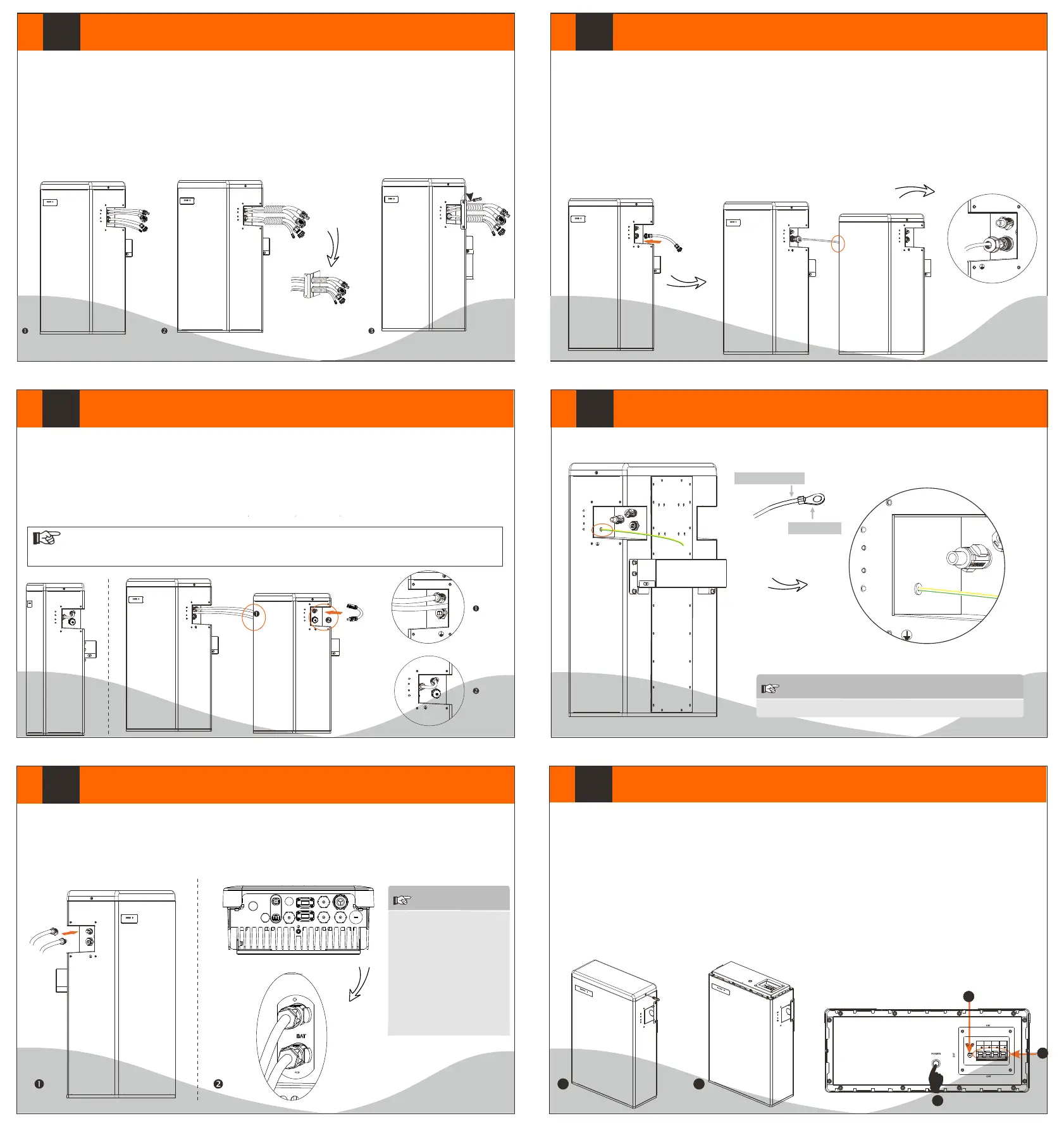
If all the battery modules are installed, follow these steps to put it
in operation.
1. Remove the upper cover board of T-BAT H 5.8;
2. Remove the small cover plate;
3. Rotate the DIP to corresponding number with small tool
accroding to the number of battery pack(s) that has(have) been
installed (please see the configuration on the right);
4. the circuit breaker to ON ;Switch
5. Press the POWER button to turn on the T-BAT system;
6. Put the small cover plate back;
7. Reinstall the upper cover board to T-BAT H 5.8;
8. Power on the Inverter.
X
VI
IX
Cable size: 10AWG.
ring terminal
1
3
4
5
2
1. Connect the cables.
2. the cables through the corrugated pipe.Run
3. DO REMEMBER TO INSERT THE SERIES-CONNECTED CABLE AT “-” AND “YPLUG” ON THE RIGHT SIDE OF LAST
BATTERY MODULE TO COMPLETE THE INTERNAL CIRCUIT.
4. Set the cables into the groove of metal plates and screw them back to the battery module on both sides.
The terminal point for GND connection is on the side of grooves as shown below:
-
YPLUG
RS485 II
-
YPLUG
RS485 II
CAUTION!
GND connection is mandatory!
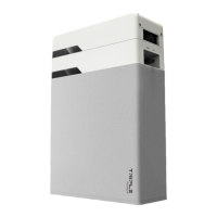
For T-BAT H 5.8:
1. Insert the series-connected cable at “-” and “YPLUG” on the right side of T-BAT H 5.8 to make a complete the internal circuit.
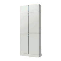
For T-BAT H 5.8 + 1~3 battery packs:
1. Connect “-” on the right side of T-BAT H 5.8/HV11550 to “+” on the left side of the next battery packs.
2. Connect “YPLUG” on the right side of T-BAT H 5.8/HV11550 to “XPLUG” on the left side of the next battery packs.
3. The rest battery packs are connected in the same way.
4. Insert the series-connected cable at “-” and “YPLUG” on the right side of last battery packs to make a complete circuit.
Power Cable Connection
Ground Connection
Overall Installation
For T-BAT H 5.8:
1. Insert one end of the BMS communication cable without cable nut directly to the BMS port of Inverter.
2. Insert the other end of the BMS communication cable to the BMS connector; then assemble cable gland and tighten cable cap.
For T-BAT H 5.8 + 1~3 battery packs:
1. Connect RS485 II of the first battery module (as show on the right) to RS485 I on the next battery module (as shown on the left).
DIP Configuration:
0- Matching T-BAT H 5.8 (default)
1- Matching T-BAT H 5.8 + 1*HV11550
2- Matching T-BAT H 5.8 + 2*HV11550
3- Matching T-BAT H 5.8 + 3*HV11550
Power Cable Connection
Communication Cable Connection
1. Connect the the positive cable (+) and negative cable (-) to the AT+ and BAT- respectively as shown in the following figure. B
2. Keep the Inverter off. Connect the other end of charging cables (+,-) to the correct port on the Inverter.
-
+
BAT- BAT+
BMS
+
-
WiFi
RF
485
BMS
Upgrade
AC
BAT
DRM
Meter
-
YPLUG
RS485 II
-
YPLUG
RS485 II
-
YPLUG
RS485 II
XPLUG
+
RS485
2. Assemble cable gland and tighten cable cap.
-
YPLUG
RS485 II
-
YPLUG
RS485 II
-
YPLUG
RS485 II
+
XPLUG
RS485 I
NOTE
Each power has one cable
terminal block connected
after leaving the factory,
and customers need to
connect the other end of
terminal block by themselves.
Please refer to 4.5.2 Cable
Connection Steps on User
Manual page 20 to get
more instruction.
Note!
Regardless of how many battery modules the user install, please put a waterproof cap on the unconnected communication
port of the battery module.
V
VII
VIII
 Loading...