Packing List
I
II
Installation Prerequisites
III
Wiring for Rack Installation
IV
Ensure that the installation location meets the following conditions:
The building is designed to withstand earthquakes
The location is far the sea to avoid salt water and humidity, over 3280.84 ft/1000 mfrom
The floor is flat and level
There are no flammable or explosive materials, at a minimum of 2.95 ft/0.9 m
The ambience is shady and cool, away from heat and direct sunlight
The temperature and humidity remain at a constant level
There is minimal dust and dirt in area
There are no corrosive gases present, including ammonia and acid vapor
Where charging and discharging, the ambient temperature ranges from 32℉/0°C to 113℉/45°C
ŸŸŸŸŸŸŸŸŸŸ
Ÿ
Ÿ
Ÿ
Ÿ
Ÿ
Ÿ
Ÿ
Ÿ
In practice, the requirements of battery installation may be different due to enviroment and locations.
In that case, follow up the exact requirements of the local laws and standards.
BMS (TBMS-MCR0800):
Rack Installation
For details, please refer to the User Manual.
Step 1. Assemble rack
Note: The Quick Installation Guide briefly describes the required installation steps. If you have any question,
please refer to the User Manual delivered with BMS for more details.
Quick Installation Guide
—— Triple Power Lithium-ion Battery
50 Ah, 72Ah
Accessories for Cabinet
L-shaped Transverse
Support x 2
M6*L16 x 4
Cassette Nut x 8
Step 2. Put the battery module into the rack, and screw it
with M6 × L16
M6 X L16 * 4
Torque: 4-5 N·m
Step 3. Add the rack and battery module
① Put the Front and Rear Sides
② Screw both sides with Cap Nuts
③ Place the metal plate
Metal plate
④ Put the battery module
⑤ Screw M6×L16
M6 X L16 * 4
Torque: 4-5 N·m
Step 5. Repeat the Step 4 to install the remaining battery
modules and BMS
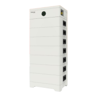
After finishing installation, it is shown as follows:
Caution!
There are two disassembly methods, with details as follows:
1. In case the entire device needs to be replaced, remove it from the top down, including Rack;
2. In case one of the battery modules needs to be maintained, remove such a battery module, reinstall it after finishing
maintenance. If there is any other battery that needs to be maintained, repeat the above-mentioned steps.
Power Cable
Communication Cable
Ground Wire
1. Connect battery to battery, and battery to BMS
Power cable: BAT+ of BMS
to BAT+ of inverter
Communication cable: BMS of
BMS to BMS of inverter
Power cable: BAT- of
BMS to BAT- of inverter
2. Connect BMS to inverter
■ BMS to Inverter
As users insert a power cable, the users should hear a click
which indicates that the cable connector is properly inserted
into the port.
Note!
The Triple Power battery module is rated at IP20 and thus can be installed outdoors as well as indoors. However, if
installed outdoors, the battery pack shall not be exposed to direct sunlight and moisture.
Note!
If the ambient temperature exceeds the operating range, the battery pack will stop running to protect itself.
The optimal temperature range for operation is -4℉/-20°C to 122℉/50°C. In the allowable range, the relative
humidity range should be between 0% and 90% RH. Frequent exposure to harsh temperatures may deteriorate its
performance and lifetime.
Note!
For the first installation, the interval among manufacture dates of battery modules shall not exceed 3 months.
Note!
OneBattery Module (TP-HR25/TP-HR36 × 1):
Accessories for Quick Rack:
Front Side x 1
Rear Side x 1
Metal Plate x 1
Cap Nut x 4
Communication Cable x 1
Power Cable x 1
Ground Wire x 1
Quick Installation Guide x 1
M6*L16 x 4
Note: The accessory with the “*” mark indicates that it will not be provided by our company, with 1.2 meters for 2 to 6
battery modules and 2.2 meters for 7 to 13 battery modules. Users can purchase from SolaX based on their own needs.
Note!
Power cable (red): BAT+ of BMS to BAT+ of inverter
Power cable (black): BAT- of BMS to BAT– of inverter
Lock Button
Press and hold the “Lock Button” while
unplugging the power cable. Otherwise, it
cannot be pulled out.
Caution!
Communication cable: Connecting BMS's BMS and the
inverter's BMS
The grounding wire must be connected.
Caution!
Sequence
1 2 3 4 5 6 7 8
BMS
/
/
BMS_H
BMS_L
/
A1
B1
GND
■ Making a BMS communication cable
If users want to make a BMS communication cable or a BMS
communication cable is required to be made before wiring, to ensure
normal operation of BMS and inverter, please read the following carefully.
The specific definition of the communication cable is shown as follows:
The wire order of the communication cable is as follows:
1 2
3
4
5
6 7 8
1) Orange stripes on white
2) Orange
3) Green stripes on white
4) Blue
5) Blue stripes on white
6) Green
7) Brown stripes on white
8) Brown
The BMS communication cable shall have a shield layer.
Note!
Communication Cable x 1
Power Cable (Black) x 1
Power Cable (Red) x 1
M6*L16 x 4
Ground Terminal x 2
Cable Tie x 3
Documentation x 2
The connector connecting to inverter from BMS is delivered with the inverter, for details, please refer to the inverter's
User Manual.
Note!
Power Cable (1.2 m) *
Power Cable (2.2 m) *
Front side
L
ocation hole
L
ocation pin
Front
Back side
Location pin
L
ocation hole
Rear
Metal plate
Back side
Front side
L
ocation hole
Location pin
L
ocation pin
L
ocation hole
Torque: 4-6 N·m
Cap Nut * 4