V
VI
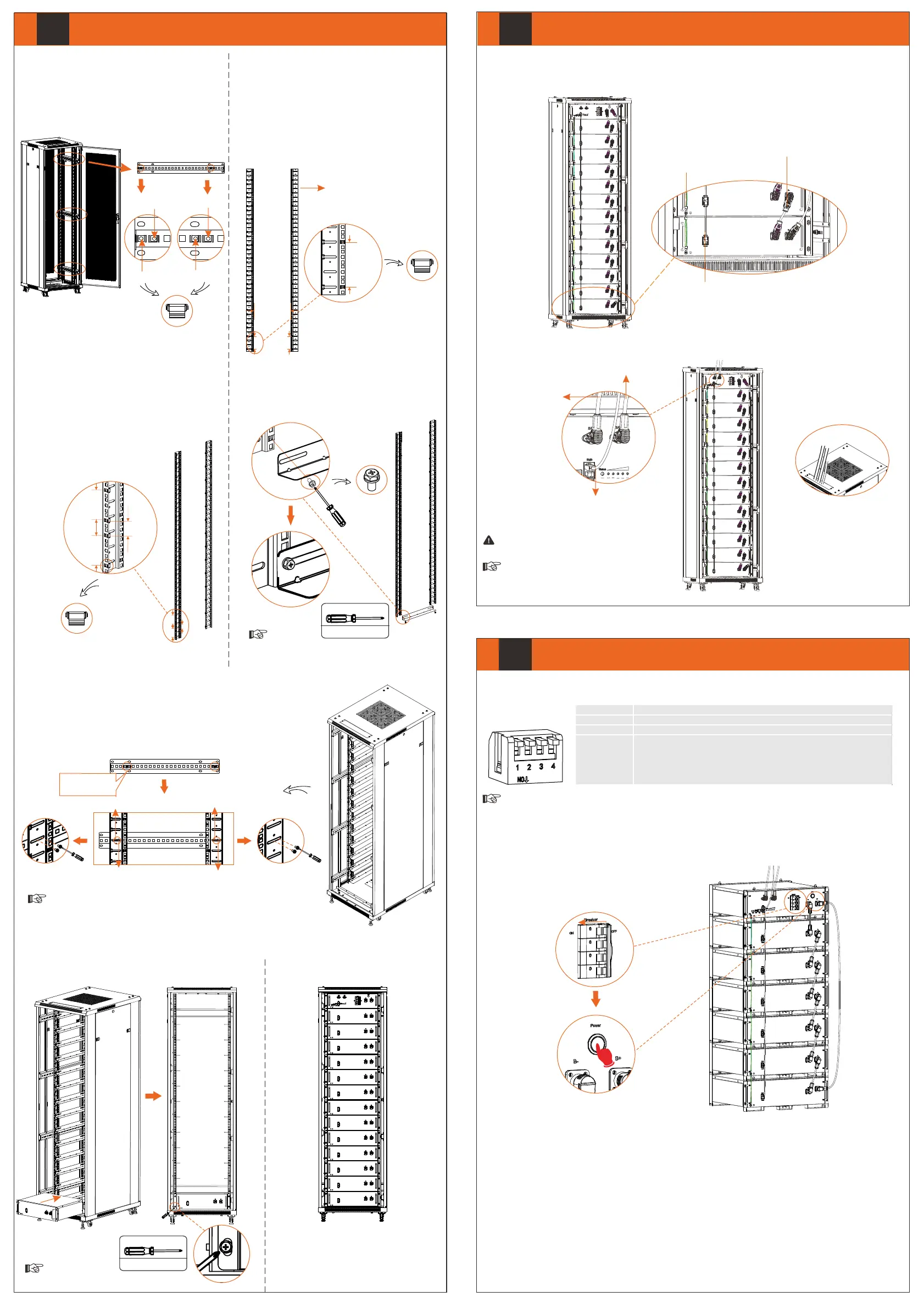
Wiring for Cabinet Installation
VII
Commissioning
Cabinet Installation
As for the installation of outside cabinet, please follow the
guide delivered with the cabinet.
Note: When installing outside cabinet, Cassette Nuts shall
be inserted before installing Fixed Rails, with 4 Cassette
Nuts for one Fixed Rails. There are totaling 3 Fixed Rails.
See figure below.
Step 2. Insert Cassette Nuts into holes on the front
Mounting Rail facing the cabinet door, with totaling 28
Cassette Nuts of one front Mounting Rail.
① Insert the first Cassette Nut;
② Insert the second Cassette Nut 2U from the first;
③ Insert the third Cassette Nut 1U from the second;
④ Then repeat ② and ③.
Step 3. Fix and screw the L-shaped Transverse Support on
the Mounting Rails with Cross External Hexagon Screw
(M6*L16 X 4) (Torque: 4-5 N·m). Make sure the two
Mounting Rails on one side are at the same level.
Step 5. Place battery modules into the cabinet, and screw them
(Torque: 4-6 N·m)
Step 6. Repeat the Step 5 until BMS has been
put into the cabinet.
Regarding installing PV terminal to the power cables and making a BMS communication cable, please refer to “IV Wiring
for Rack Installation”.
1. Connect battery to battery, and battery to BMS
Power Cable
Communication Cable
Ground Wire
2. Connect BMS to inverter
320102038401
M6 X L16 * 2
Torque: 4-5 N·m
The two location holes on the L-shaped Transverse
Support are long, please attach the screws at the end of
holes near mounting rail.
Note!
Step 4. After all L-shaped Transverse Support are secured,
(1) Attach the assembled Mounting Rails into the cabinet, making sure all four Mounting
Rails are at the same level.
(2) Fix the assembled Mounting Rails on Fix Rail by using 4 screws (delivered with the
cabinet), and insert 2 screws into the 4th and 5th location holes near the front side, and
2 screws into the 1st and 2nd holes near rear side.
• Please prevail in kind.
• Cassette Nuts shall be inserted before installing the assembled
Mounting Rails, with 4 screws for one Fixed Rails.
• Ensure that heavy duty castors are tight and firm.
Note!
• DIP Switch
The DIP switch is equipped on BMS.
Black Start: In case of pressing and hold the POWER button for less than 20 sec, the status light will flash green light for 1 sec
and then turn off for 4 sec, with a period of 5 sec. After pressing and holding the POWER button for 20 sec, the status light will
come on solid green light, and the SOC power indicators will flash as follows: 1) the 3rd indicator (from left to right) flashes
yellow light, and the remaining indicators are off; 2) the 2nd and 4th indicators flash yellow light, and the remaining indicators
are off; 3) the 1st and 5th indicators flash yellow light, and the remaining indicators are off; 4) all the power indicators are off.
The whole process will last for 0.4 sec.
But, we do not recommend to use the Black Start as it may cause communication port to be charged, resulting in an electric
shock.
Before commissioning, please check to ensure that, the installed battery modules are the same model battery module, and all
the ground wires, power cables and communication cables are connected.
Power ON
After finishing wiring,
1. Turn the Breaker on;
2. Press the POWER buttom for 5 sec, to start system.
■ If the batteries have not been used for more than 9 months, these batteries must be charged to at least SOC 50 % each
time.
■ For the first installation, the interval among manufacture dates of battery modules shall not exceed 3 months.
■ If a battery is replaced or added for capacity expansion, each battery's SOC should be consistent. The max. SOC
difference should be between ±5%.
■ If users want to increase their battery system capacity, please ensure that the SOC of the existing system capacity is
about 40%. The manufacture date of the new battery shall not exceed 6 months; in case of exceeding 6 months, please
charge the new battery to around 40%.
The DIP switch 4 is pressed at the factory settings.
To adjust the DIP switch, a small flat-head screwdriver shall be prepared by users themselves.
Note!
Communication cable: BMS of BMS to BMS of inverter
(Note: The Link port on the BMS is for parallel
connection only. DO NOT use for any other purposes.)
Power cable:
BAT+ of BMS to
BAT+ of inverter
Power cable: BAT- of BMS
to BAT- of inverter
As users insert a power cable, the users should
hear a click which indicates that the cable
connector is properly inserted into the port.
Note!
The grounding wire must be connected.
Caution!
After completing wiring, these cable
shall be through the threading hole
on the caber plank.
Front
Rear
Cables
As for the installation of inside cabinet, please follow the
steps as below.
There are two alternative sizes (22U and 42U) of cabinets
available for users. The following steps take 42U (1U = 4.445
cm) with 13 battery modules as an example.
Step 1. Insert Cassette Nuts into the holes on the Mounting
Rails (*4) every 3U (1U = 4.445 cm), with totaling 14
Cassette Nuts of one Mounting Rail. The distance between
two Mounting Rails on one side shall be at about 12.99
inches/330 mm.
Front sideRear side
Second
First
Fourth
Fifth
M6 X L16 * 4
Torque: 4-6 N·m
Please prevail in kind.
Note!
Side View of Cabinet
The four Mounting Rails are in
the Package C of NCB Network
Cabinet.
(Cassette Nuts *14) x
( Mounting Rail * 4)
Front Rear
12.99 inches
330 mm
3U
3U
First Cassette Nut
Second Cassette Nut
Third Cassette Nut
Forth Cassette Nut
2U
1U
2U
Front
Rear
(Cassette Nuts *28) x
( Mounting Rail (front) *2)
Front
Rear
Adjust
Refer to the
step above
Front side Rear side
Fourth
Fifth
First
Second
Front side
Rear side
DIP switch 1 A reserved function
DIP switch 2 A reserved function
DIP switch 3 A reserved function
Terminal resistance
Note: 1. The DIP switch 4 shall be flipped down (open the circuit) when
connecting BMS to inverter; 2. In case of parallel connection, only shall the
DIP switch 4 on the last BMS be flipped down (open the circuit), and the DIP
switch 4 on the rest of BMS shall be flipped up (close the circuit).
 Loading...