Mode of Operation
Stop signal opens motor contactor
C
1
that in turn initiates the closing
of brake contacts C
2
.
The Thyristor is switched on and
fire (to inject DC current to the
motor) after time delay, to induce
the braking current.
The torque, which is a function
of the DC current, can be
controlled
by the firing angle of the
Thyristor.
Note: there is a time delay
between opening of one
contactor and closing the other
one to reduce the EMF. The time
delay correlate to the size of the
motor.
Braking Time
Braking time depends on the inertia, friction of the load,
speed, and braking current. The required braking time is
best established by practical experience.
The Solbrake / SMB offers two operating modes,
Automatic and Manual. Selection between the modes is
one by an internal dip switch. d
Dip sw.
Operation Mode
On Manual
O
ff Automatic
It is recommended to use the Automatic mode (factory
default setting) to reduce the braking time and minimize
motor heating.
Automatic operation
DC injection duration is
automatically controlled
by the Solbrake / SMB.
Injection ceases when
Motor has come to a
complete stop.
Manual operation
DC injection duration is
according to the Braking
Time setting on the front
panel.
Notes:
1. Motor heating during braking is similar to heating
during Direct On Line starting. Therefore, always
adjust for the shortest DC injection time duration.
2. In general, for improved braking process to be in effect,
it is recommended to apply some minimal inertia on the
motor shaft.
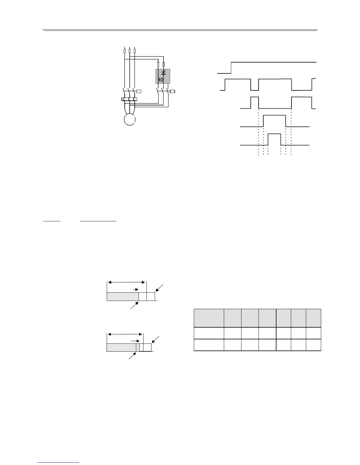
The Solbrake / SMB incorporates the following built-in
time delays:
t
1
DC Injection
Brake Contactor
Motor Contactor
1 - 2 Open
t
2
t
3
t
4
t
5
1 - 2 Closed
Power ON
Motor
Running
Braking
Process
Start Sto
M
Where:
t
1
- Time delay between opening of motor's contactor C
1
and closing of brake contactor C
2,
allowing motor's
back EMF to diminish (see table below).
t
2
- Time delay of 0.05 sec between closing of brake
contactor C
2
and initiation of DC current, to ensure
that brake contactor does not switch DC current,
enabling the use of regular AC contactor.
t
3
- In Auto Mode – Enabling of DC current injection.
In Manual Mode - time of DC current injection.
Range: 1-10 sec.
t
4
- Time delay between end of DC current injection and
opening of brake contactor C
2
to ensure that the
contactor does not switch DC current, enabling the
use of regular AC contactor (see table below).
t
5
- Time delay of 0.2 sec. between opening of brake
contactor C
2
and enabling motor's restart.
Approximate Time Delays (sec).
Sec.
10
1
DC Injection
Motor Stopped
Braking contactor Closed
Restart Enable
Solbrake
/ SMB
8
17
58
105
210
390
t
1
0.2
0.3
0.6
1.1
1.7
2.5
t
4
0.2
0.2
0.3
0.8
1.2
1.9
Sec.
10
1
DC
Injection
Motor Stopped
Braking contactor
Restart Enable
Torque at standstill
When required to maintain the DC braking current after the
motor has come to a complete stop, set Auto/Man Dip
Switch to On (Manual operation). Set Braking Time to a
longer time than it takes the motor to come to a complete
stop.
Note - DC Injection after motor has come to a complete
stop may cause excessive heating of both the motor and the
brake.
5
 Loading...