Do you have a question about the Sole Diesel SCO 5 and is the answer not in the manual?
Describes remote control capabilities and safety precautions for the SCO.
Explains the meaning of various symbols used throughout the manual.
Details the mounting and connection process for the SCO 5 panel.
Details the mounting and connection process for the SCO 10 panel.
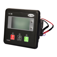
Describes the buttons and LEDs on the SCO 5 control panel.
Explains the structure of displayed information and navigation between pages.
Introduces the types of events and alarms that can appear in the history log.
Lists and describes engine events with corresponding symbols and hours.
Lists and describes various warning conditions and their associated symbols.
Lists the conditions that cause a shutdown and their display states.
Details specific shutdown events such as Emergency Stop and Overspeed.
Details additional shutdown events like Overfrequency and Short Circuit.
Provides a table detailing terminal codes, signal types, and descriptions for connections.
Describes the buttons, LEDs, and indicators on the SCO 10 panel.
Explains navigation between pages and the types of screens available.
Details the 'Measurement' page showing various operational parameters.
Guides on how to access controller information and system settings.
Provides instructions for updating maintenance hours after a warning.
Explains how to view and interpret the engine's historical log data.
Describes how alarms are displayed and the procedure for confirmation.
Instructions on how to adjust the contrast of the panel's display.
Step-by-step guide to changing the language settings of the control panel.
Overview of available alarms: Breaker Open/Cooling, Warning, and Shut Down.
Details the specific 'Breaker Open and Cooling' alarm condition.
Explains the nature and purpose of 'Warning' alarms.
Describes the conditions that trigger a 'Shut Down' alarm.
Explains protection against incorrect voltage phase connections.
Overview of the different operational states of the genset.
Lists and describes the various engine status states during operation.
Lists electrical events, their protection types, and available information.
Details additional electrical events and their corresponding protection mechanisms.
Lists more electrical events and their associated protection types.
Provides specifications and function table for coolant temperature sensors.
Provides specifications and function table for oil pressure sensors.
Details specifications for two-pole oil pressure sensors.
Details specifications for temperature switches.
Details specifications for oil pressure switches.
Describes the optional amperometric pack for phase current measurement.
Details the second panel kit for remote operation of the SCO 10.
Provides the electrical wiring diagram for the SCO 5 panel with monophasic gensets.
Provides the electrical wiring diagram for the SCO 5 panel with triphasic gensets.
Provides the electrical wiring diagram for the SCO 10 panel with monophasic gensets.
Provides the electrical wiring diagram for the SCO 10 panel with triphasic gensets.
| Glow Plug Indicator | Yes |
|---|---|
| Oil Pressure Indicator | Yes |
| Water Temperature Indicator | Yes |
| Tachometer | Yes |
| Hour Meter | Yes |