EasyManua.ls Logo

Solid State Logic SiX Channel 500 Series - User Manual

Solid State Logic SiX Channel 500 Series
8 pages
Print Icon
To Next Page IconTo Next Page
Loading...
-1-
SiX Channel Module
for 500 Series Enclosures
User Guide
Question and Answer IconNeed help?

Do you have a question about the Solid State Logic SiX Channel 500 Series and is the answer not in the manual?

Summary

Safety and Installation Considerations

General Safety

General safety instructions, warnings, and precautions for operating the apparatus.

Caution

Specific cautions regarding the use and servicing of the apparatus.

Installation

Instructions for safely installing the apparatus into a rack.

Standards and Warranty

Standards Compliance

Details standards compliance and regulatory information for the apparatus.

Instructions for Disposal of WEEE

Guidelines for proper disposal of electronic waste according to EU regulations.

Limited Warranty

Information on how to claim warranty and where to find full details.

Introduction and Operation

Introduction

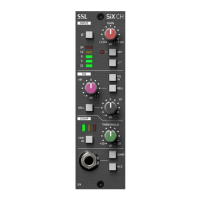
Congratulates the user and introduces the SSL SIX Channel Module.

SuperAnalogue Pre-Amp Input

Details the SuperAnalogue pre-amp design and its input facilities.

Input Details

Mic Input (Rear XLR connector)

Describes the microphone input using SSL's SuperAnalogue design and phantom power.

Line Input (Front Panel TRS)

Describes the front panel line input and its impedance options.

Block Diagram

Channel EQ

Explains the features and operation of the two-band EQ section.

Compressor

Details the 'one knob' compressor, its controls, and performance.

Overview

The Solid State Logic SiX Channel Module is a single-width 500 Series mini channel strip designed for use in 500 Series compatible enclosures, such as the API lunchbox® or equivalent. This module integrates SuperAnalogue channel processing features from SSL's SiX console, including a Mic-pre, low and high-frequency EQ, and a single-knob compressor. Its primary function is to expand the input capabilities of professional audio setups, offering additional Mic/Line inputs to line-level returns of any professional audio device, including the Stereo channels of the SiX console. It also provides a flexible solution for creating a professional modular mixer when used with a 'summing' 500 Series rack unit. The nominal input/output level for this module is +4 dBu.

SuperAnalogue Pre-Amp Input

The SiX Channel features a SuperAnalogue pre-amp, a design derived from the mic pre-amps found in larger SSL Duality and AWS consoles. This wide-gain-range, ultra-low-noise design supports both Line and Mic inputs. Unlike consoles with separate pre-amps for line and mic, the SiX Channel uses a single pre-amp with a "Line" gain range switch to accommodate a broad spectrum of source levels.

  • Mic Input (Rear XLR connector): The default microphone input utilizes SSL's SuperAnalogue design and includes individually switched 48V phantom power. The nominal impedance for the Mic (XLR) input is 1.2 kΩ, with the rear 500 Series enclosure XLR serving as the default input.
  • Line Input (Front Panel TRS): The input source can be switched to the front panel ¼" TRS jack line input by pressing the '[Line]' switch on the channel. The nominal Line Input impedance is 10 kΩ, which can be increased to 1 MΩ using the Hi-Z switch. This 1 MΩ impedance makes the input suitable for high-impedance sources like passive guitar pickups, eliminating the need for an external DI box.
  • Gain Control: A single Gain control adjusts the pre-amp gain. For the microphone pre-amp, the gain ranges from +6 dB to +72 dB. For the Line amp, the gain ranges from -3 dB to +63 dB. The active range depends on the selected input source.
  • High Pass Filter (HPF): Following the pre-amplifier, a switched 12 dB/oct, 75 Hz High Pass Filter (HPF) is included. This filter helps reduce unwanted low-frequency content such as microphone rumble or AC noise.
  • Polarity Switch (Ø): A Polarity Switch (Ø) inverts the polarity of the rear XLR Mic Amp, providing a 180° phase shift.
  • LED Meter: A five-segment LED meter displays the output signal level in dBu, offering visual feedback on the signal strength.

Channel EQ

The EQ section on the SiX Channel module is based on the design found in the SiX Console, which itself draws inspiration from SSL's classic E series EQ. It is a gentle, broad-stroke two-band design featuring high and low shelving filters. The high-frequency filter operates at 3.5 kHz, and the low-frequency filter operates at 60 Hz. Both bands offer an adjustable gain range from +15 dB to -15 dB.

  • Bell Switch: Each band can be independently switched between shelving and bell curves using the BELL switch. A notable feature of the bell curves is that they automatically shift their center frequencies. The high-frequency bell curve operates at 5 kHz, and the low-frequency bell curve operates at 200 Hz, enhancing the versatility of the two controls.
  • EQ 'IN' Switch: The EQ circuit can be switched 'in' or completely bypassed using the 'IN' switch. This ensures that the channel's flat frequency response is not affected by the tolerance of the EQ control center detent positions when the EQ is not in use.

COMP (Compressor)

The 'one knob' channel compressor on the SiX Channel module is designed for responsive and versatile performance despite its simple controls.

  • Attack and Release: The compressor has an approximate attack time of 5 ms and an over-easy/soft knee response, allowing for smooth operation across various audio content. The release time is approximately 300 ms, and the ratio is fixed at 2:1.
  • Threshold Control: The single user control adjusts the compressor Threshold, which is adjustable between +10 and -20 dBu.
  • Gain Reduction Meter: A three-LED meter indicates the amount of gain reduction being applied by the compressor.
  • Automatic Make-Up Gain: The circuit includes automatic make-up gain to maintain a consistent signal level across the full range of threshold settings.
  • Compressor 'IN' Switch: Similar to the EQ circuit, the compressor can be completely bypassed using the IN switch. This allows for easy comparison between compressed and uncompressed signals and prevents component tolerances from affecting the sound of the channel strip when the Threshold is set to minimum.

Maintenance Features

The manual emphasizes several important safety and installation considerations to ensure a safe working environment and proper device function.

  • General Safety: Users are instructed to read and keep the instructions, heed all warnings, and follow all instructions. The device should not be used near water or exposed to rain or moisture. Cleaning should only be done with a dry cloth. Ventilation openings must not be blocked, and installation should follow the rack manufacturer's instructions.
  • Internal Components: There are no user-adjustments or user-serviceable items inside the apparatus. Adjustments or alterations may affect performance and compliance standards. The apparatus is not intended for safety-critical applications.
  • Caution: The device should only be used within the scope of API 500 series compatible racks. Operation with covers removed is prohibited. Servicing, other than what is explicitly stated in the installation instructions, should only be performed by qualified service personnel to reduce the risk of electric shock.
  • Installation: Before fitting or removing the apparatus from the rack, power must be removed from the rack. The module should be secured into the rack using the panel fixing screws supplied with the rack.

Standards Compliance and Disposal

The SiX Channel Module is designed for installation and use in CE marked API 500 series compatible racks, indicating compliance with EMC and the Low Voltage Directive (2006/95/EC). For disposal in the European Union, the product is marked with the WEEE symbol, indicating it should not be disposed of with other waste. Users are responsible for handing it over to a designated collection point for recycling electrical and electronic equipment to conserve natural resources and protect human health and the environment.

Limited Warranty

Warranty claims should be referred to the supplier. Full warranty information for equipment supplied directly by Solid State Logic is available on their website. The company reserves the right to change features and specifications without notice due to ongoing research and development. Solid State Logic is not responsible for any loss or damage arising from errors or omissions in the manual.

Solid State Logic SiX Channel 500 Series Specifications

General IconGeneral
Type500 Series Channel Strip
Number of Channels1
Phantom PowerYes
PadYes
Input TypeMic/Line
Inputs1 x XLR (mic), 1 x 1/4" (line)
Output TypeBalanced
Outputs1 x XLR
Other I/OSidechain Insert (TRS)
Module Size500 Series
High Pass Filter75Hz
Power Requirements500 Series compliant power supply