
S
Sandra HicksJul 31, 2025
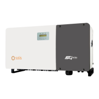
What to do if my SOLIS Solis-100K-5G has no power?
- MMichael TerryJul 31, 2025
If your SOLIS Inverter isn't powering on, verify the PV input connections are secure. Then, check the DC input voltage (it should be greater than 120V for single phase or greater than 350V for three phase systems). Finally, ensure that the PV positive and negative connections are not reversed.