520
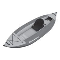
1. Mango suave
2. Cubierta en arco
3. Anillo “D” del asiento
4. Asiento ajustable
5. Correa
6. Piso HPI
7. Válvula
8. Válvula de drenaje
9. Aleta desmontable
10. Cubierta de popa
11. Velcro
DIBUJO
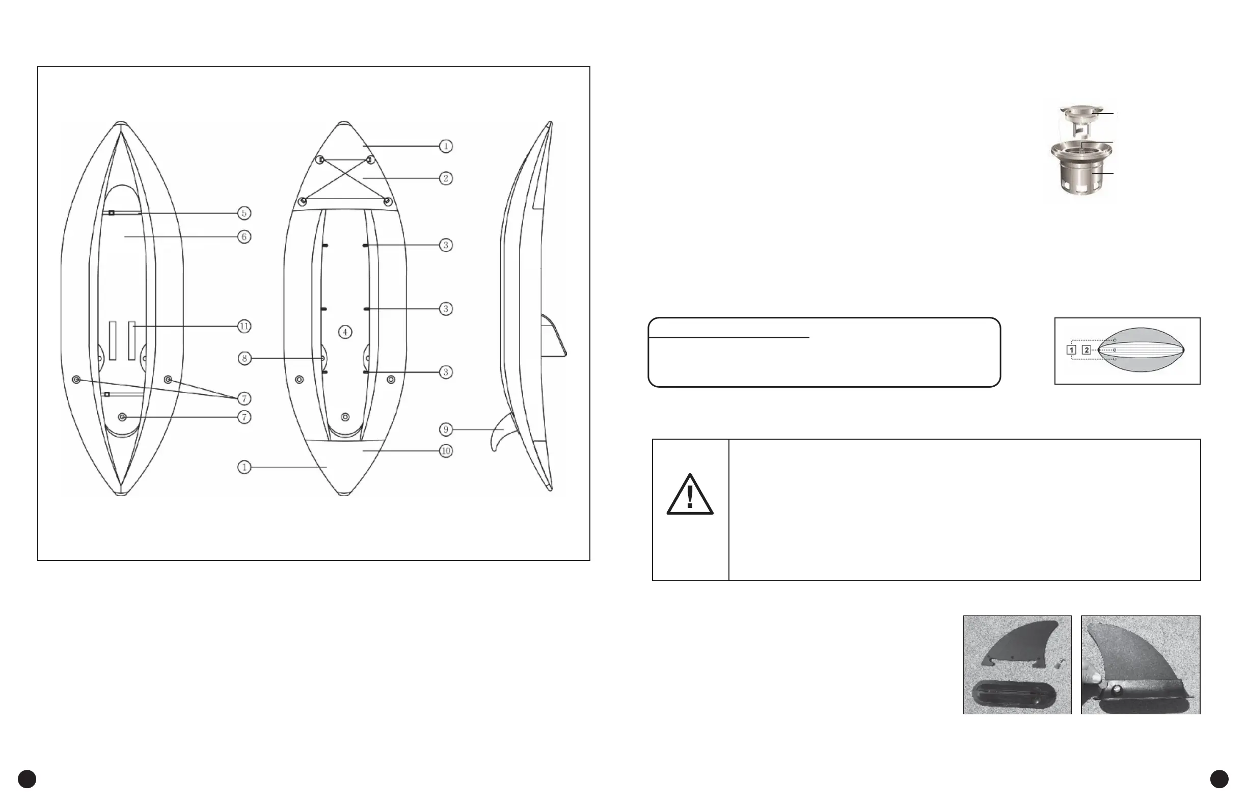
REMOVABLE SKEG
Any use of an air compressor may result in poor performance or damage to the kayak,
and automatically voids all warranties. If you leave your kayak exposed to the hot sun,
check the pressure and deate it slightly. Otherwise the kayak may become over inated
and stretch the material.
The ambient temperature aects the tube’s internal pressure :
a variation of 1° C / 1.8° F causes a variation of the pressure in the tube of
+/- 4 mBar (0.06psi).
WARNING
Included with the Solstice kayak is a removable n. The
base is pre-attached to the kayak and the n is secured
with a recessed screw & nut. The removable n can be
installed using a coin or screwdriver. This can be done
with the kayak inated or deated. It is recommended to
inate it rst. Insert the front hook on the n in the base,
push back and down. With the n aligned properly,
install hex nut and screw, tighten using a coin or
screwdriver.
BEFORE ASSEMBLY AFTER ASSEMBLY
ASSEMBLY INSTRUCTIONS / INFLATION / DEFLATION
1. Find a at area and make sure that the area you have selected to set up the kayak is completely free of
stones, sticks, sharp objects or other foreign debris.
2. Carefully unfold the kayak, spreading out the tubes to make them as smooth as possible.
a. Caution: do not drag the kayak across the ground as it may tear
it or cause other damage. Solstice is not responsible for
damage caused to kayak due to mishandling or failure to follow
these instructions.
3. Inate your kayak with pump (#19125AC) from Solstice or any pump
designed for inatable boats with a Halkey - Roberts valve.
a. Caution: Do not use high-pressure air compressors.
4. Valve Operation: Reference Figure 1-A (Right)
a. INFLATION
Unscrew the valve cap (1). Push button (2) in and turn approximately 90 degrees so it is in the “out” position.
Insert the pump hose end piece and inate it until you reach the required pressure.
After ination tighten all the valve caps (clockwise). Only the valve cap(s) can ensure nal air tightness.
b. DEFLATION
To release air from the side tubes and bottom oor tube, remove the valve cap(1) and push button(2) in
and turn approximately 90 degrees so it is in the “in” position.
5. MAX. AIR PRESSURE:
a. Side Tubes: 0.25 bar / 3.60 psi (=250 mbar ).
b. Bottom / Floor Chamber: 0.50 bar / 7.25 psi (=500 mbar ).
c. Warning: Do not over inate.
6. Ination Sequence: Reference Figure 1-B (Right)
a. Inate side tubes 1st and oor chamber last
(1) Valve Cap
(2) Button
(3) Valve Base
Figure 1-A
Figure 1-B
 Loading...