3.1.3 Tool holder clamping
The spindle must necessarily be
to a complete stop before ma-
neuvering the changing system
tools.
Operation:
Keeping the tool holder clam-
ped in the spindle cone is made
through a clamping device.
The effort to pull the tool in the
spindle is obtained thanks to a
stack of washers elastic type.
The release is done with a
pneumatic cylinder (pressure
service: 5 bar).
Connection:
The pressure air connection is
located at the rear part of the
unit (quick connect tube Ø6).
Before rotating the spindle, the
pneumatic cylinder must be in
its rear position (feed the return
jack, tube Ø6) and the detector
must have detected its position.
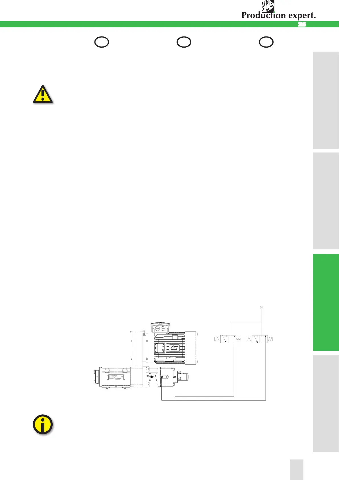
Example of pneumatic connec-
tions from the cylinder:
Somex S.A.S recommends
installing two 3/2 electro-
valves as shown above for
pneumatic ejection.
3.1.3 Spannen des Werkzeu-
ghalters
Die Spindel muss unbedingt
im völligen Stillstand sein, bevor
das Werkzeugspannsystem
betätigt wird.
Funktion:
Die Werkzeughalter werden
in der Spindel mittels einem
Spannsystem eingezogen. Das
Spannen erfolgt über Tellerfe-
dern, das Entspannen erfolgt
über ein Pneumatikzylinder (Be-
triebsdruck: 5 bar)
Anschluss:
für Schlauch Ø6 mm im hinte-
ren Bereich der Einheit Bevor
die Spindel zu drehen beginnt,
muss der P1 Anschluss des
Zylinders unter Druck gesetzt
werden (Anschluss Ø6 seitlich)
und es muss gewährleistet sein,
dass der Endschalter die hintere
Position des Zylinders erkennt.
Beispiel für den Anschlus des
hydraulischen Zylinders:
Somex S.A.S empfiehlt den
Einbau von zwei 3/2 Ma-
gnetventile , wie oben für die
pneumatische Ausstoß .
3.1.3 Serrage du porte outil
La broche doit impérativement
être à l’arrêt complet avant toute
manoeuvre du système de
changement d’outils.
Fonctionnement:
Le maintien des outils dans le
cône de l‘unité se fait grâce à
un serreur. L‘effort de traction
sur le porte-outil dans la broche
est obtenu grâce à un empilage
de rondelles de type élastiques.
Le desserrage se fait grâce à un
vérin pneumatique (pression de
service: 5 bar)
Raccordement:
Raccord qui se trouve à l‘arrière
de l‘unité (raccord rapide pour
tube Ø6). Avant la mise en rota-
tion de la broche, il faut alimen-
ter le retour vérin (raccord rapide
pour tube Ø6) qui se trouve sur
les chambres et s‘assurer que
le détecteur détecte la position
arrière du vérin.
Exemple de branchements du
vérin:
Somex S.A.S préconise
l’installation de deux élec-
trovannes 3/2 telle que re-
présentée ci-dessus pour
l’éjection pneumatique.
17
1. Ind. relative à la sécurité
1. Sicherheitshinweis
1. Notes on safety
2. Mise en service
2. Inbetriebnahme
2. Commissioning
3. Utilisation / Exploitation
3. Handhabung / Betrieb
3. Handling / Operation
4. Maintenance / Entretien
4. Instandhaltung / Wartung
4. Service / Maintenance
DEFR GB
3. Utilisation / Exploitation
3. Handhabung / Betrieb
3. Handling / Operation
 Loading...