Do you have a question about the SOMFY Animeo Series and is the answer not in the manual?
Defines a manual command as generated by local push buttons or Somfy RTS transmitter.
Defines an automatic command via telegram on specific objects.
Controls Venetian blind via US ergonomics using push buttons or RTS transmitter.
Controls Venetian blind via EU ergonomics using push buttons or RTS transmitter.
Controls end product via screen ergonomics using push buttons or RTS transmitter.
Defines actions for On, Off, and Toggle telegrams on KNX group addresses.
Illustrates slat positions for Venetian blinds.
Guidance on selecting an appropriate location for installation.
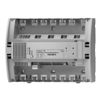
Visual guide for mounting the motor controller unit.
Instructions for connecting wiring and power supply.
Visual representation of electrical connections for the device.
Explains the meaning of the "US"-LED blinking status.
Details cable types, lengths, and stripping for connections.
Pre-set move times and push button input assignments.
Explains the use of the Reset/Prog button for basic settings.
Allows setting push button ergonomics via Reset/Prog button before ETS programming.
Step-by-step guide to changing ergonomics using the Reset/Prog button.
Setting motor move/turn times via local push buttons before ETS programming.
Learning intermediate position 1 via local push buttons or ETS parameters.
Procedure for saving intermediate position 1.
Procedure for calling intermediate position 1.
How to reset the device to factory settings via button or ETS.
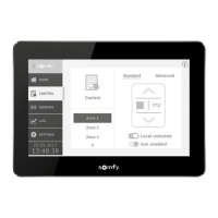
General overview of available communication objects.
General settings for motor output configuration and priority.
Defines default settings for motor outputs (Combined/Individual).
Configures automatic vs. manual operation priority.
Settings for automatic/manual function priority for motors.
Enables and configures universal binary inputs.
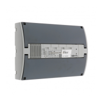
Enables and configures radio binary inputs.
Configuration for group control input.
Settings for slat orientation for Venetian blinds.
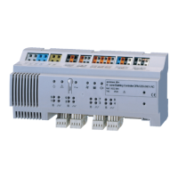
Detailed configuration for each motor output.
Selects the type of device (blind, shutter, etc.) for each motor.
Sets the maximum running time for UP/Close operations.
Sets the maximum running time for Down/Open operations.
Configures the time for complete slat tilting for Venetian blinds.
Defines the move time for a single slat turn step.
Adds time to balance mechanical tolerances for slat turns.
Defines the device's response to low priority security events.
Defines the device's response to high priority security events.
Sets the cyclic monitoring time for security objects.
Configures specific functions for motors.
Sets the UP/DOWN and Slat positions for intermediate position 1.
Defines the UP/DOWN position for IP1.
Defines the slat position for IP1.
Sets UP/DOWN and Slat positions for intermediate position 2.
Defines the UP/DOWN position for IP2.
Defines the slat position for IP2.
Blocks position orders during blind movement.
Blocks slat orders during Venetian blind turning.
Blocks UP/DOWN and IP1 commands.
Blocks step/stop and turn commands.
Blocks local push button and RTS radio commands.
Repeats the last command after a security event.
Overview of basic functions for binary inputs.
Configuration for Venetian blind Up/Down functionality.
Selects Venetian blind Up/Down as the basic function.
Defines activity time distinguishing short/long telegrams.
Configures the contact type for local input A.
Configures the contact type for local input B.
Configuration for switch/dry contact functionality.
Selects Switch/Dry contact as the basic function.
Defines edge evaluation for contact A.
Continues defining edge evaluation options for contact A.
Defines edge evaluation for contact B.
Configures sending the input state on bus power return.
Configures cyclic status transmission for contacts A and B.
Configuration for 8-Bit value input with rising edge.
Selects 8-Bit value (rising edge) as basic function.
Defines the value transmitted on rising edge for input A.
Configures contact type for input A.
Configures contact type for input B.
Defines value transmitted on rising edge for input B.
Configuration for dimming function via binary inputs.
Selects Dimming as the basic function.
Defines pressing time for dimming telegrams.
Sets the value transmitted with a short pressing of input.
Defines On/Off and Toggle behavior for inputs A/B.
Defines contact type for local input A.
Defines contact type for local input B.
Configures dimming behavior (Stop telegram, Cyclic intervals).
Defines dimming step length.
Sets the interval duration for cyclical dimming.
General settings for binary inputs.
Defines delay after bus voltage return before first telegram.
Enables telegram rate limitation.
Sets the maximum number of telegrams per time unit.
Settings for electronic motors.
Sets start-up delay for each motor output.
Defines reactions to bus power failure and return.
Reaction settings for motors 1-4 on bus power failure.
Defines position on bus power failure.
Defines position on bus power failure.
Defines position on mains power return.
Enables automatic cascading to reduce power spikes.
Configures status feedback for motor positions.
Enables feedback for upper/lower end positions.
Selects feedback type (Combined/Individual).
Defines feedback type for motor positions.
Details feedback options like Up/Down, Slat, or None.
Sets how motor position feedback is sent (On demand, Status change, Cyclic).
Sets time intervals for cyclical position feedback.
General settings for radio binary inputs.
Enables individual radio binary inputs.
Overview of basic functions for radio inputs.
Configuration for radio inputs for Venetian blinds Up/Down.
Selects Venetian blind Up/Down as the basic function.
Defines activity time for short/long radio telegrams.
Configures the "my" push button functionality.
Sets 1-Bit value for the "my" button.
Sets 8-Bit value for the "my" button.
Disables functionality for the "my" button.
Configuration for radio inputs for switch function.
Selects Switch as the basic function.
Configures functionality for the Up push button.
Configures functionality for the Down push button.
Configures functionality for the "my" push button.
Sets 1-Bit value for the "my" button.
Sets 8-Bit value for the "my" button.
Disables functionality for the "my" button.
Configuration for radio inputs with 8-Bit value.
Selects 8-Bit value (rising edge) as basic function.
Sets the value transmitted by the Up push button.
Sets the value transmitted by the Down push button.
Configures functionality for the "my" push button.
Sets 1-Bit value for the "my" button.
Sets 8-Bit value for the "my" button.
Disables functionality for the "my" button.
Configuration for radio inputs for dimming function.
Selects Dimming as the basic function.
Defines pressing time for dimming telegrams.
Defines dimming step length.
Configures functionality for the "my" push button.
Sets 1-Bit value for the "my" button.
Sets 8-Bit value for the "my" button.
Disables functionality for the "my" button.
Configuration for radio inputs for slow tilting.
Selects Venetian blind slow tilting as basic function.
Defines pressing time for slow tilting telegrams.
Defines slow tilting action for Venetian blinds.
Configures functionality for the "my" push button.
Sets 1-Bit value for the "my" button.
Sets 8-Bit value for the "my" button.
Disables functionality for the "my" button.
Technical specifications for the controller unit.
| Type | Controller |
|---|---|
| Category | Controller |
| Series | Animeo |
| Dimensions | Varies by model |
| Weight | Varies by model |
| Compatibility | Somfy motors and sensors |