Do you have a question about the SOMFY V 500 Connect and is the answer not in the manual?
Read installation and safety instructions carefully before installing this Somfy product.
Product not designed for persons with reduced capacities without supervision or prior instruction.
Radio range limitations and environmental factors affecting product performance.
Do not dispose of with household waste; take to an approved collection point for recycling.
Explanation of symbols for mains adapter installation and earthing requirements.
Clean the equipment with a soft, dry cloth after switching off the power.
Requires a 2.4 GHz Wi-Fi network; 5 GHz Wi-Fi is incompatible.
Ensure sufficient 2.4 GHz Wi-Fi range at the indoor monitor's installation location.
The connected video door phone is compatible with a maximum of 1 indoor monitor.
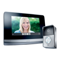
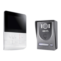
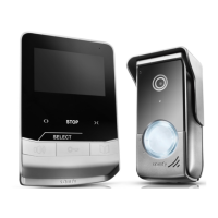
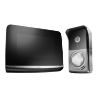
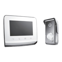
Consists of an indoor monitor and a door station, connected by a 2-wire cable.
Manage access, communicate, and control gates remotely via the "Somfy Protect" app.
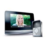
Preview visitors, communicate, and control gates/pedestrian gates from the indoor monitor.
Allows viewing visitors, using controls, accessing photos, and settings.
Enables communication with the person at the door station.
Allows saving photos from the door station and adding custom ring tones.
Indicates connection correctness or a visit when the user is absent.
Activates the screen automatically when motion or presence is detected.
Enables hearing the ring tone and the person at the door station.
Used for connecting the power supply and the door station.
Used to restart or reinitialise the video door phone, e.g., for Wi-Fi changes.
Indicates the operational status of the connected video door phone.
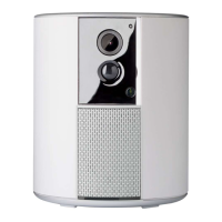
Protects the camera from the rain.
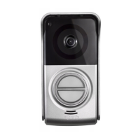
Films visitors and sends video to the monitor and smartphone (102° H, 65° V).
Provide enhanced night vision capabilities.
Automatically activates infrared LEDs when it is dark.
Allows visitors to talk to the people they are visiting.
Allows visitors to hear the people talking to them.
Indicates your name on a label, accessible after removing the call button.
Notifies the resident and sends visitor photos to the app upon pressing.
Prevents the door station from being removed without the assembly key.
Used to connect the door station to the monitor, gate drive, and electric latch.
Adjusts the volume of the door station speaker using a screwdriver.
Specifies cable types and quantities based on distance between door station and monitor.
Illustrates the overall wiring setup for the video door phone system.
Indicates the maximum number of junction boxes allowed for wiring runs.
Recommends installing door phone and gate motor cables in separate protective sheaths.
Notes that the necessary cables are not supplied with the product.
Information on controlling Somfy RTS gate motors via dry contact and radio control.
Step-by-step guide for screwing the mounting bracket to the wall.
Instructions on how to strip protruding wall cables and route them correctly.
Inserting power supply cables into terminal blocks DC 24V and CS/Call station.
Ensuring cables are correctly inserted into terminal blocks by gently pulling them.
How to fasten the monitor to the wall bracket by sliding it downwards.
Install at approx. 1.60m and avoid placing camera opposite a light source.
Route all cables in the rain shield and fasten it to the wall/pillar.
Connect indoor monitor cable, electric latch, and gate drive cables to terminals.
Place the door station in the rain shield and screw it using the assembly key.
Steps to turn call button, access name plate, write name, and reassemble.
Ensure call station is wired to gate motor or electric latch for remote control via app.
Compliance with EN 12453 for safe use of motorised doors and gates.
Connect door station dry contact output (COM/NO) to drive electronics terminals.
Connect terminal blocks L- and L+ of the door station to the electric latch.
Switch the gate drive on first, then the connected video door phone.
Mains adaptor must be installed no more than 8m from the monitor and be accessible.
Screen activates on movement detection or touch; settings are stored after power loss.
Overview of functions: Live view, Photos, Gate control, Pedestrian gate, Settings.
Control up to 5 RTS products or groups within range of the monitor.
Use screwdriver to turn button on back of door station to increase or decrease volume.
Toggle audible beep by pressing the call button for 5 seconds.
Receive notifications, communicate, control gates remotely, and view visit history via the app.
Steps to download the app, create an account, and add the device.
Steps to open the app, go to 'My devices', and add the new connected video door phone.
Reinitialise the video door phone and follow app instructions to change the Wi-Fi network.
Restart the device remotely via the app or locally via the monitor using the reset pin.
| Door Lock Control | Yes |
|---|---|
| Gate Control | Yes |
| Night Vision | Yes |
| Connectivity | Wi-Fi |
| Mobile App | Yes |
| Compatibility | Somfy |
| Type | Video Intercom |