2
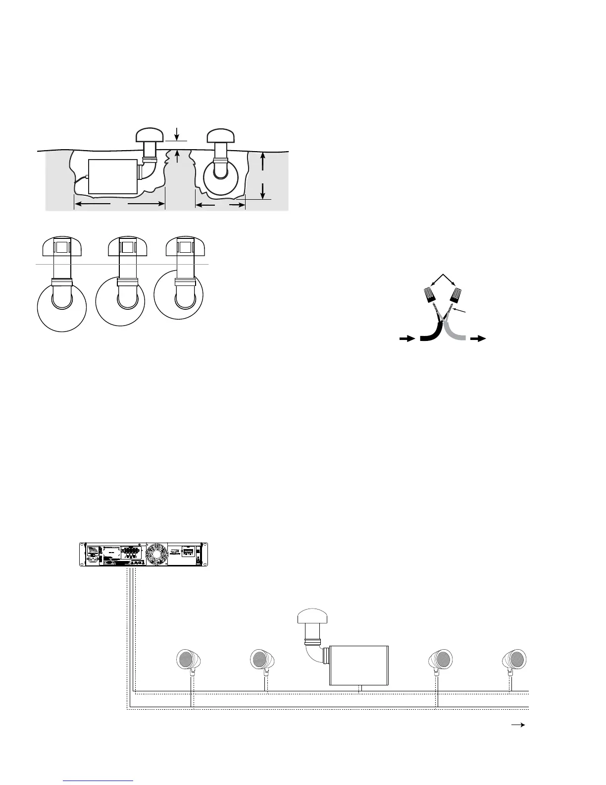
Subwoofer Installation
1. Locate the subwoofer in an area that will not ood with standing
water.
2. Dig the hole using the guide. See gure 2
LS10SUB: A=4” B=26” C=16” D=13”-16”
LS12SUB: A=4” B=35” C=18” D=15”-18”
Note: (for variable depth see Figure 3 below)
3. Prepare a ‘bed’ for the subwoofer that is reasonably free of
voids and large rocks.
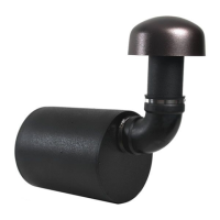
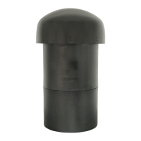
4. Install and secure the rubber elbow onto the canopy and ABS
tube subassembly using one of the supplied hose clamps.
5. Install the rubber elbow and canopy assembly on the subwoofer
enclosure; do not tighten the second hose clamp at this point.
6. Place the subwoofer into the ground.
7. Rotate the cabinet as required so that the bottom of the canopy
will be 4” above the nished grade after backll.
8. Once the subwoofer is in the correct location tighten the hose
clamp at the connection between the enclosure and the rubber
elbow.
A
B
C
D
I N S T A L L AT I O N O P T I O N S
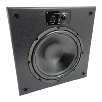
The off-center port design allows for easy
variable-depth installation of the fully sealed
PVC Woofer Enclosure.
GROUND
LEVEL
Figure 2
Figure 3
Twist
Wires
Together
Waterproof
Wire Nuts
From Speaker To Amplifier
Positive
+
Negative
-
Figure 4
Connecting to the Amplier
70 volt audio systems allow for speakers to be daisy chained
together. In a typical system with one zone of audio you simply run a
stereo or 4 conductor wire from the amplier to the closest speaker.
Once you have designated your rst speaker as either left or right,
continue alternating the wires between the left and right channels
creating a daisy chain of stereo satellites. The Subwoofer can be
wired anywhere in the chain. See gure 5.
Note: Sonance strongly recommends the use of 14
gauge, or larger, direct burial grade wire.
Caution: The amplifier should not be connected to AC
power until all connections are completed. High power
70volt amplifiers present a serious shock hazard. Do not
connect speaker wires to the amplifier until all other
connections are completed.
9. Dig a 4” – 5” deep trench to run the speaker wires in.
10. Run the wire through the trench from your amplier to the rst
speaker location.
11. Connect the direct burial wire to each speaker wire, connections
should be made with either silicone lled wire connectors or
appropriate junction boxes. See Figure 4.
IMPORTANT: Be sure not to let any stray ‘+’ and ‘–’
strands touch each other. Touching strands can cause a
short-circuit that could damage your amplifier.
Note: Confirm that you have connected speaker “+” to
amplifier “+” and speaker “–” to amplifier “–”.
12. After all the speakers connections are completed, connect the
wires to your amplier. See Figure 5 for reference.
13. Turn your amplier on and test the system with your favorite
music. If the speakers are operating properly, rell the wire
trench and enjoy your new speakers.
SLS Wiring Diagram 70V
ExpandableConfiguration: 4 SATs to 1 SUB or up to 8 SATs to 1 SUB
Crown CDi Series Amplifier
LS47SATs & LS10SUB or LS67SATs & LS12SUB
Left LeftRight Right
Figure 5
Note: The subwoofer can
be connected at any point
in the daisy chain.
 Loading...