7
Controls, Functions and Connections
Front Panel Refer to Reference Diagrams (Page 4).
C Power Switch This push button provides control over the AC power from your wall outlet. When OFF
(out position) nothing on the amplifier is functional. When ON (depressed) the amplifier
will operate normally.
D Standby Switch This push button when OFF (out position) will allow normal operation of the amplifier
(indicated by the green Standby LED (F), assuming Power ON). When depressed ON the
amplifier will be placed in STANDBY mode and will not be operational (indicated by the
red standby LED, assuming Power ON). In this mode, a small amount of current will
remain flowing through the output tubes - this reduces power consumption and extends
tube life during periodic short term non-use periods (i.e. during a listening session when
interruptions occur, or a short time prior to a listening session so the amplifier is warm
and ready). This mode also will keep optimal warm up times of the tubes as short as
possible. For periods between listening sessions extending over a 12 hour period, it is
recommended that the Power 1 is turned off via the Power Switch (C). The amplifier can-
not be biased up in this STANDBY mode.
E Power LED When this LED is off, so is the amplifier. When the LED is glowing red, both channels are
Muted, controlled by the Input Selector Switches (I). When the LED is green, the amplifier
is receiving power and both inputs are selected, the amplifier is ready for operation.
(Green Power LED indicates ON; Red Power LED indicates ON but in MUTE mode;
Green + Red (Orange) indicates one channel is in Mute & one channel is selected).
F Standby LED When this LED is off, so is the amplifier. When the LED is glowing red, this indicates the
amplifier is in Standby mode, controlled by the Standby Switch (D). When the LED is
green the amplifier is in operate mode.
Rear Panel Refer to Reference Diagrams.
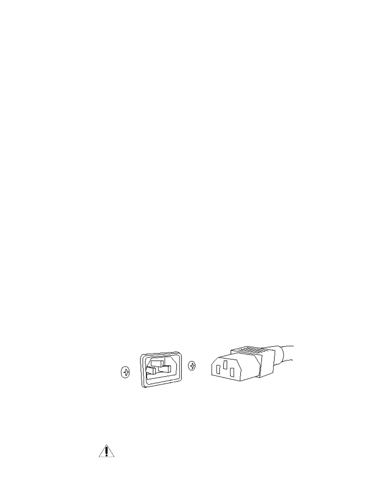
G Detachable Power Plug the detachable Power Cord into this socket. The Power 1 amplifier is configured
Cord Socket for the operating voltages in which they are sold. See shipping box or sticker on rear of
the chassis for voltage settings. If a different operating voltage is required, please contact
an authorized Sonic Frontiers dealer or the factory directly.
H Fuse Location This socket/holder houses a 3.5 amp slo-blo fuse for countries with AC supplies
rated between 100-120V or a 1.6 amp slo-blo fuse for countries operating on
a 220-240V supply.
REPLACEMENT FUSES MUST BE RATED WITH THE SAME SPECIFICATIONS
AS THE ORIGINAL FUSE.