SonTek
ADP Software Manual Version 6.42 (November 1, 2000)
7
Water Salinity (ppt): (Enter value)
Salinity is used to calculate the speed of sound, which converts Doppler shift to water velocity.
Speed of Sound (m/s): (Derived value)
The speed of sound in water is given in the menu for information only, and cannot be changed by
the user. It is computed from the values of temperature and salinity. Sound speed shown in this
menu is based upon the entered values of temperature and salinity; if temperature mode is set to
MEASURED, the sound speed will be based upon the value from the ADP temperature sensor.
See the ADP Principles of Operation for details on the effect of sound speed on ADP operation.
Temperature Mode: (Multiple-choice)
Temperature mode refers to the source of temperature data for sound speed calculations. USER
indicates that the value input in the setup menu (see above) should be used; MEASURED
indicates that the value from the ADP temperature sensor should be used. The ADP temperature
sensor is considered sufficiently reliable and accurate (± 0.2°C) for sound speed calculations,
thus MEASURED is the common choice. The USER setting is occasionally selected to simplify
post-processing corrections using data from an external temperature / salinity sensor. Sound
speed is recorded with each profile, so post-processing corrections can be made using data from
either temperature mode.
Averaging Interval (s): (Enter value)
The ADP will accumulate samples internally for this period of time and then display and store
the mean current profile. The standard deviation (accuracy) of the velocity data is inversely
proportional to the square root of the averaging interval (longer averaging times give lower
standard deviations).
Number of Depth Cells: (Enter value)
Number of depth cells to collect per profile.
Depth Cell Size (m): (Enter value)
Vertical length of each depth cell. Standard deviation (accuracy) of the velocity measurements is
inversely proportional to the depth cell size (larger depth cells give lower standard deviations).
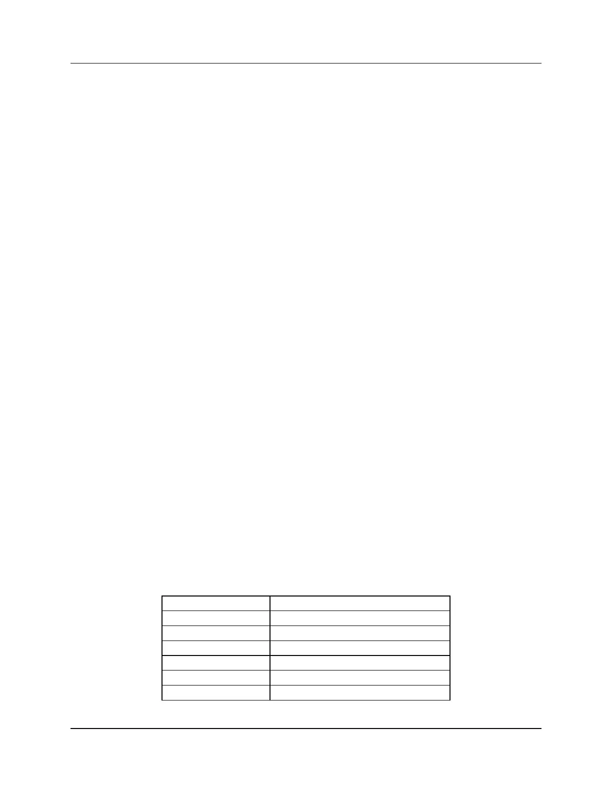
Blanking Distance (m): (Enter value)
The vertical distance from the transducers to the start of the first depth cell. A minimum value is
required for each frequency to avoid contamination. Except for specialized applications, the
blanking distance should be left at the minimum setting and not changed by the user. Minimum
values for each frequency are shown in the table below.
ADP Minimum Blanking Distances
Frequency Minimum Blanking Distance
3000 kHz 0.2 m
1500 kHz 0.4 m
1000 kHz 0.5 m
750 kHz 0.8 m
500 kHz 1.0 m
250 kHz 1.5 m