EasyManua.ls Logo

Sony AC-V500 - SECTION 1 DISASSEMBLY; 1-1. CASE; 1-2. CH BOARD, MB BOARD; SECTION 2 DIAGRAMS

Sony AC-V500
14 pages
Print Icon
To Next Page IconTo Next Page
To Previous Page IconTo Previous Page
Loading...
REARS
URE
ay
LEE
SRT
ROR
ERAT
FA
NM
RTS
TEEN
RSA
NT
ARENT
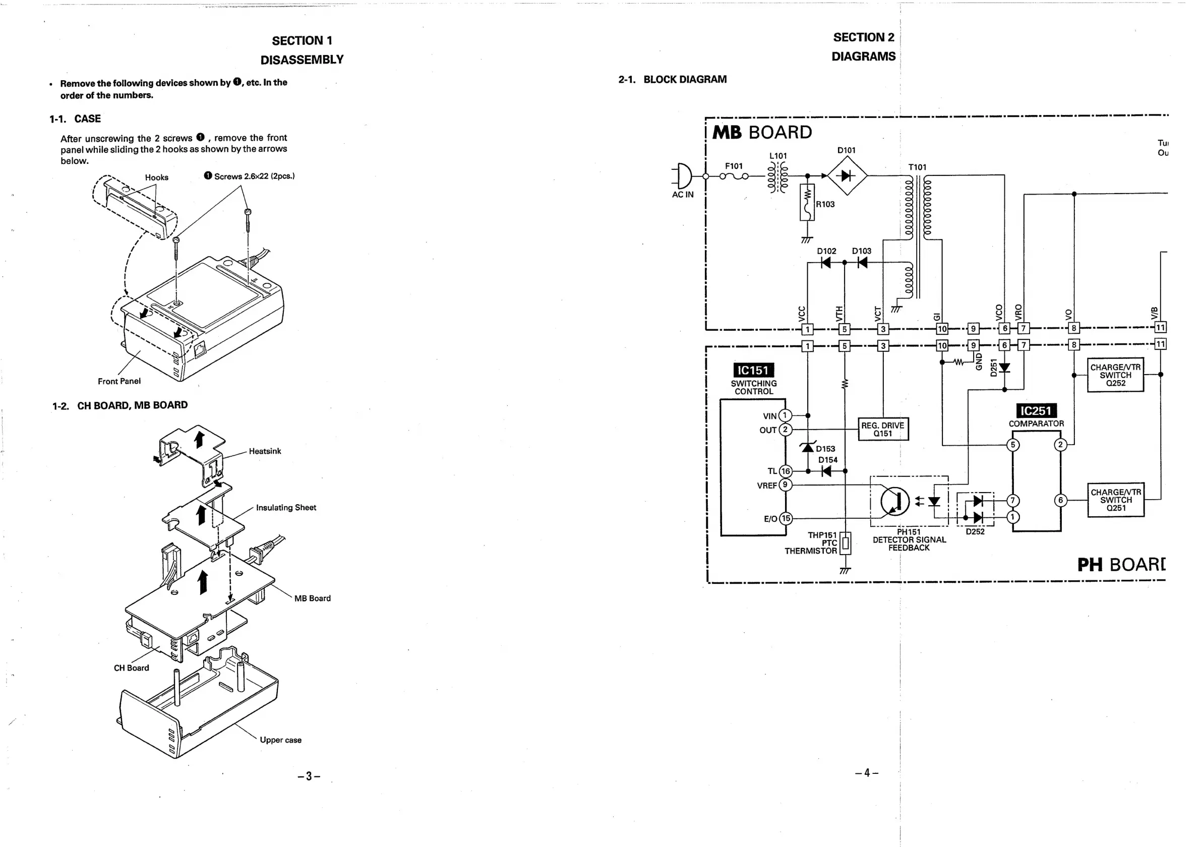
SECTION
1
DISASSEMBLY
-
Remove
the
following
devices
shown
by
@,
etc.
In
the
order
of
the
numbers.
1-1.
CASE
After
unscrewing
the
2
screws
@
,
remove
the
front
panel
while
sliding
the
2
hooks
as
shown
by
the
arrows
below.
|
a
Hooks
—
O
Screws
2.6x22
(2pes.)
Front
Panel
1-2.
CH
BOARD,
MB
BOARD
Heatsink
Insulating
Sheet
MB
Board
Upper
case
_s
|
2-1.
BLOCK
DIAGRAM
AC
IN
>
|
F101
SE
-
.
7101
SS
ee
mer
Cee
ee
ete
Cs
ae
SECTION
2
|
DIAGRAMS
|
|MB
BOARD
|
L101
D101
R103
VQOOOOOO00'
VYUQVOVYV9IOO
D102 D103
00000
po
SWITCHING
CONTROL
:
PH151
pe
Ul
-_
DETECTOR
SIGNAL
THERMISTOR
FEEDBACK
Tu
Ou
Oo
co
S
S
>
=
oes
8
|
Oo
6
ee
nes
=
[Bp
CHARGE/VTR
SWITCH
COMPARATOR
eee
ee
eee
ee
eee
=-—
2.
oes
oe
Q252