EasyManua.ls Logo

Sony AC-V500 - 2-3. PRINTED WIRING BOARDS

Sony AC-V500
14 pages
Print Icon
To Next Page IconTo Next Page
To Previous Page IconTo Previous Page
Loading...
AC-V500
:
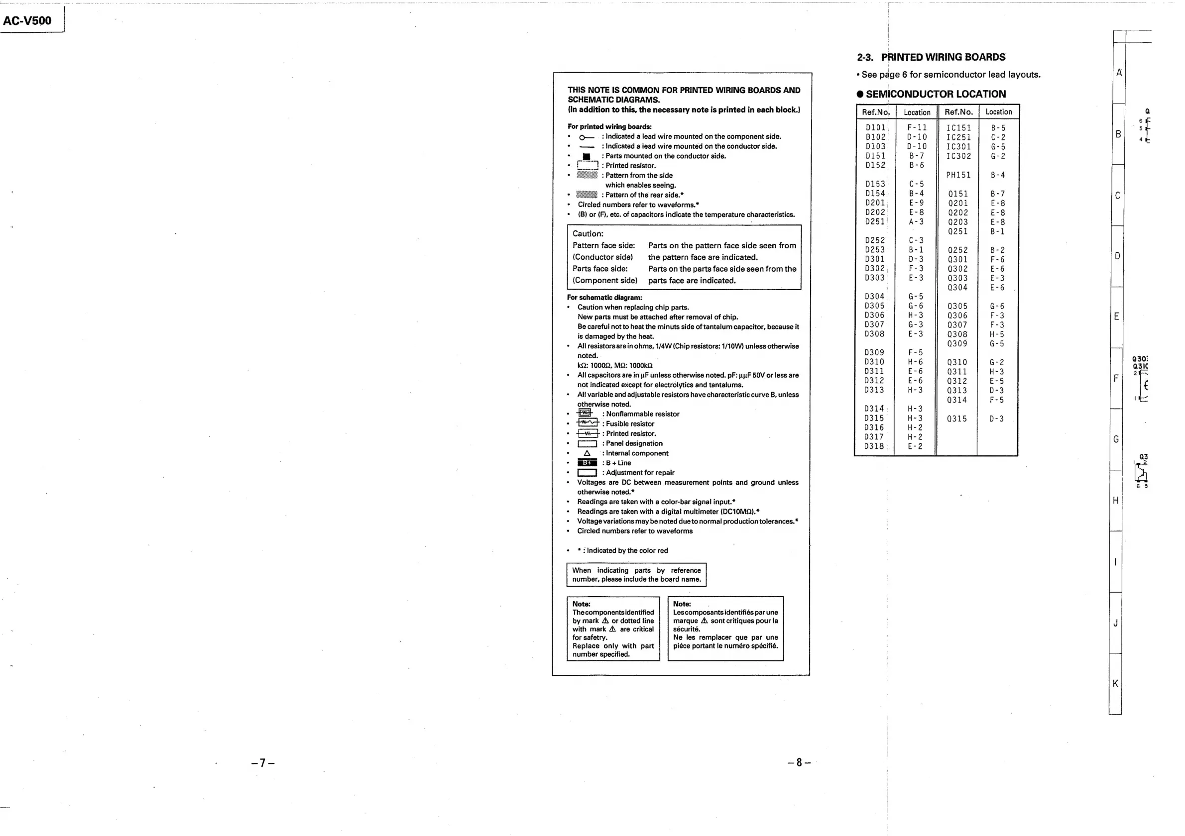
THIS
NOTE
IS
COMMON
FOR
PRINTED
WIRING
BOARDS
AND
SCHEMATIC
DIAGRAMS.
{In
addition
to
this,
the
necessary
note
is
printed
in
each
block.)
For
printed
wiring
boards:
*
O—_
:
Indicated
a
lead
wire
mounted
on
the
component
side.
*
——_
:
indicated
a
lead
wire
mounted
on
the
conductor
side.
:
Parts
mounted
on
the
conductor
side.
:
:
Printed
resistor.
:
Pattern
from
the
side
which
enables
seeing.
*
Eee=
:
Pattern
of
the
rear
side.*
¢
Circled
numbers
refer
to
waveforms.*
¢
{B)
or
(F),
etc.
of
capacitors
indicate
the
temperature
characteristics.
Caution:
Pattern
face
side:
Parts
on
the
pattern
face
side
seen
from
(Conductor
side)
the
pattern
face
are
indicated.
Parts
face
side:
Parts
on
the
parts
face
side
seen
from
the
(Component
side)
_
parts
face
are
indicated.
For
schematic
diagram:
¢
Caution
when
replacing
chip
parts.
New
parts
must
be
attached
after
removal
of
chip.
Be
careful
not
to
heat
the
minuts
side
of
tantalum
capacitor,
because
it
is
damaged
by
the
heat.
¢
Allresistors
arein
ohms,
1/4W
(Chip
resistors:
1/10W)
unless
otherwise
noted.
.
kQ:
1000Q,
MQ:
1000kQ
°
All
capacitors
are
in
uF
unless
otherwise
noted.
pF:
nuF
50V
or
less
are
not
indicated
except
for
electrolytics
and
tantalums.
¢
All
variable
and
adjustable
resistors
have
characteristic
curve
B,
unless
otherwise
noted.
°
:
Nonflammable
resistor
:
Fusible
resistor
:
Printed
resistor.
:
Panel
designation
't
Internal
component
:B+Line
:
Adjustment
for
repair
¢
Voltages
are
DC
between
measurement
points
and
ground
unless
otherwise
noted.*
¢
Readings
are
taken
with
a
color-bar
signal
input.*
¢
Readings
are
taken
with
a
digital
multimeter
(DC10MQ).*
¢
Voltage
variations
may
be
noted
due
to
normal
production
tolerances.*
*
Circied
numbers
refer
to
waveforms
GO
*
:
Indicated
by
the
color
red
When
indicating
parts
by
reference
number,
please
include
the
board
name.
Note:
Note:
Thecomponentsidentified
Les
composants
identifiés
par
une
_
by
mark
A\
or
dotted
line
marque
A\
sont
critiques
pour
la
with
mark
A\
are
critical
sécurité.
for
safetry.
|
Ne
les
remplacer
que
par
une
Replace
only
with
part
piéce
portant
le
numéro
spécifié.
number
specified.
|
|
|
2-3,
PRINTED
WIRING
BOARDS
«See
page
6
for
semiconductor
lead
layouts.
@
SEMICONDUCTOR
LOCATION
[Reto
|
tosslon
[
RetiNo,
|
Ueetion