EasyManua.ls Logo

Sony AV-3600 - 5-4. Playback Preamplifier Adjustment

Sony AV-3600
110 pages
Print Icon
To Next Page IconTo Next Page
To Previous Page IconTo Previous Page
Loading...
5-4.
Playback
Preamplifier
Adjustment
(Head
Resonance
and
Playback
Equalization)
Frequency
characteristics
of
the
playback
am-
plifiers
are
adjusted
to
equalize
head-to-tape
character-
istics
and
to
obtain
the
desired
overall
frequency
response.
Test
Point/
Board:
Adjust
for:
Adjustment/
Board:
Equipment
Required:
TP-201/V2
(PBrf
output)
Correct
frequency
response
as
shown
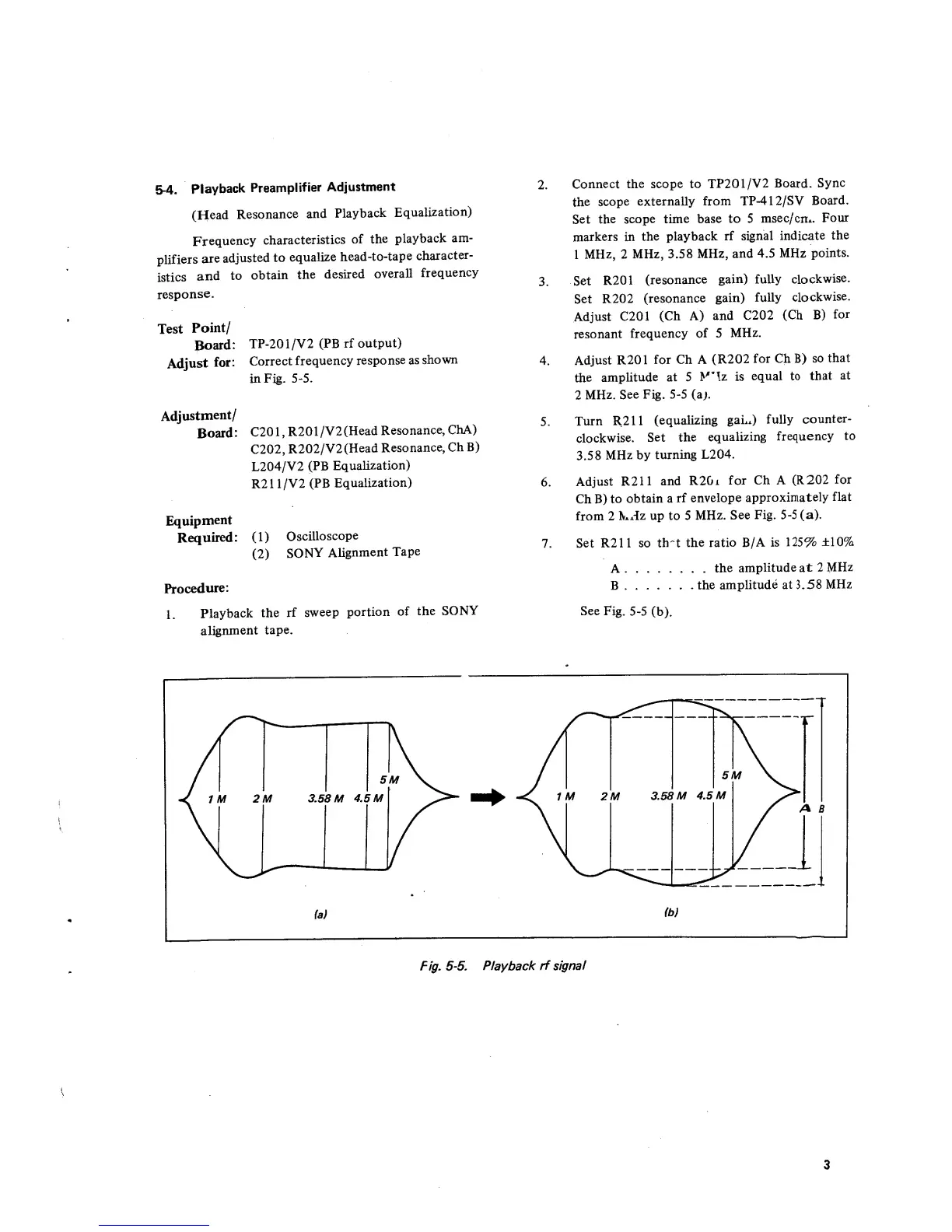
in Fig.
5-5.
C20
1
, R20
1 /
V2
(Head
Resonance,
ChA)
C202,
R202/V2(Head
Resonance,
Ch
B)
L204/V2
(PB
Equalization)
R21
1/V2
(PB
Equalization)
(1)
Oscilloscope
(2)
SONY
Alignment
Tape
Procedure:
1.
Playback
the
rf
sweep
portion
of
the
SONY
alignment
tape.
2.
Connect
the
scope to
TP201/V2
Board.
Sync
the
scope
externally
from
TP-412/SV
Board.
Set
the
scope time
base
to
5
msec/cm.
Four
markers
in
the
playback
rf
signal indicate
the
1
MHz, 2
MHz,
3.58
MHz,
and
4.5
MHz
points.
3.
Set
R201
(resonance
gain) fully
clockwise.
Set R202
(resonance
gain)
fully
clockwise.
Adjust C201
(Ch A)
and C202
(Ch
B)
for
resonant
frequency
of
5
MHz.
4.
Adjust R201
for Ch A
(R202
for Ch B)
so
that
the
amplitude
at
5
M*!z is
equal
to
that
at
2
MHz.
See
Fig.
5-5
(a>.
5.
Turn
R
:
211
(equalizing
gaLx)
fully
counter-
clockwise.
Set
the
equalizing
frequency
to
3.58
MHz
by
turning
L204.
6.
Adjust R211
and
R2Gi
for
Ch
A (R202
for
Ch B)
to
obtain
a
rf
envelope
approximately
flat
from
2
kHz
up to
5
MHz.
See
Fig.
5-5
(a).
7.
Set
R211 so
trrt
the
ratio B/A
is 12596
±10%
A
the
amplitude at 2
MHz
B
the
amplitude
at 3.58
MHz
See
Fig.
5-5
(b).
(a)
A B
(b)
Fig.
5-5.
Playback
rf
signal

Table of Contents