Do you have a question about the Sony BC-L100 and is the answer not in the manual?
Provides a general introduction to the BC-L100/L100CE battery charger.
Details the key capabilities and functions of the battery charger.
Explains the charging process for lithium-ion and Ni-Cd batteries.
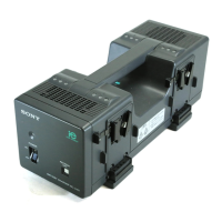
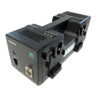
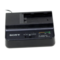
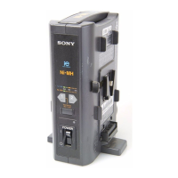
Identifies and describes the physical controls, indicators, and connectors.
Covers the procedures for charging various battery types.
Lists important safety and usage guidelines for charging.
Provides step-by-step instructions for connecting and removing batteries.
Details the charging sequence and operation for different battery types.
Lists the technical data, power requirements, and dimensions of the charger.
Outlines the procedure for taking the unit apart for servicing.
Diagram showing the placement of internal circuit boards.
Information on component identification, availability, and units.
Procedure for adjusting the charger's standard voltage output.
Procedure for calibrating the discharge current.
Procedure for calibrating the charging current.
High-level block diagram of the charger's internal circuitry.
Detailed circuit diagram for the main 'A' board.
Detailed circuit diagram for board 'B'.
Detailed circuit diagram for board 'C'.
Detailed circuit diagram for board 'D'.
Detailed circuit diagram for board 'E'.
Detailed circuit diagram for board 'F'.
Pinout diagrams for various semiconductor components used in the unit.
General notes on component identification, replacement, and ordering procedures.
Diagram illustrating the assembly and identification of all parts.
Procedure for testing electrical leakage from metal parts to ensure safety.
| Brand | Sony |
|---|---|
| Model | BC-L100 |
| Category | Battery Charger |
| Language | English |