Do you have a question about the Sony CDP-CX400; CDP-CX450 and is the answer not in the manual?
General operational and power requirements of the CD player.
Technical details for the compact disc player mechanism.
Details on audio and digital output capabilities.
Procedures to ensure safety after service, focusing on AC leakage.
Information for identifying the unit model, often found on the back panel.
Precautions for handling sensitive optical components to prevent damage.
Procedures for checking laser diode emission and focus operation.
Instructions for using a test disc to verify CD-TEXT display functionality.
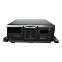
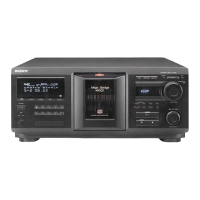
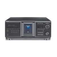
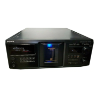
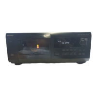
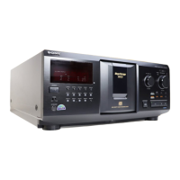
Identification of front panel controls, buttons, and indicators.
Steps to remove the upper case and main board assembly.
Procedures for removing the front panel and table components.
Steps for disassembling base, pop-up, and back panel assemblies.
Steps for removing the CD mechanism drive assembly.
Modes for testing automatic disc playback and operations like loading and rotation.
Modes for displaying system info, unit configuration, and adjustments.
Mode for servo adjustments and calibration procedures.
Mode to verify key inputs and display functionality.
Adjustments related to the disc loading and pop-up mechanisms.
Adjustments related to electrical signal levels and waveforms.
Visual representation of circuit boards and functional block diagrams.
Detailed schematics for various sections of the unit.
Diagrams of IC functions and detailed pin assignments.
Exploded views of the outer casing and chassis structure.
Exploded views of front panel and CD mechanism parts.
| Type | CD player |
|---|---|
| Frequency Response | 2 Hz - 20 kHz |
| Analog Output | RCA |
| Remote Control | Yes |
| Disc Capacity | 400 |
| Playable Media | CD |
| Channels | 2 |
| Output Level | 2.0V |