— 2 —
TABLE OF CONTENTS
1. SERVICING NOTE
.......................................................... 3
2. GENERAL .......................................................................... 4
3. DISASSEMBLY
3-1. Front Panel ........................................................................... 9
3-2. Illumination ASSY ................................................................ 9
3-3. Base Unit and Magnet Holder............................................. 10
3-4. CD Mechanism Section ...................................................... 11
4. TEST MODE ..................................................................... 12
5. MESHANICAL ADJUSTMENTS .............................. 15
6. ELECTRICAL ADJUSTMENTS ............................... 18
7. DIAGRAMS
7-1. Circuit Boards Location ...................................................... 20
7-2. Printed Wiring Board — BD Section —............................. 21
7-3. Schematic Diagram — BD Section — ............................... 23
7-4. Printed Wiring Board — Main Section —.......................... 26
7-5. Schematic Diagram — Main Section — ............................ 29
7-6. Printed Wiring Board — Panel Section — ......................... 32
7-7. Schematic Diagram — Panel Section — ............................ 35
7-8. IC Pin Functions ................................................................. 38
7-9. IC Block Diagrams ............................................................. 44
8. EXPLODED VIEWS
8-1. Case Section........................................................................ 46
8-2. Front Panel Section ............................................................. 47
8-3. Chassis Section ................................................................... 48
8-4. Mechanism Deck Section 1 (CDM-46) .............................. 49
8-5. Mechanism Deck Section 2 (CDM-46) .............................. 50
8-6. Optical Pick-up Section (KSM-213 BFN/M-NP)............... 51
9. ELECTRICAL PARTS LIST ........................................ 52
CAUTION
Use of controls or adjustments or performance of procedures
other than those specified herein may result in hazardous ra-
diation exposure.
The laser component in this product
is capable of emitting radiation
exceeding the limit for Class 1.
This appliance is classified as
a CLASS 1 LASER product.
The CLASS 1 LASER
PRODUCT MARKING is
located on the rear exterior.
This caution label
is located inside
the unit.
4-987-981-01
4-987-981-11
4-987-981-21
4-987-981-31
4-987-981-41
4-987-981-51
4-989-203-01
4-989-203-11
4-989-203-21
4-989-203-31
4-989-203-41
4-989-203-51
CX50 : US model
CX50 : Canadian model
CX50 : AEP, G model
CX50 : Australian model
CX50 : E model
CX50 : Singapore model
CX571 : US model
CX571 : Canadian model
CX571 : E model
CX571 : Singapore, Australian model
CX571 : AEP, G model
CX571 : UK model
PARTS No.
MODEL
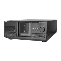
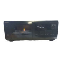
MODEL IDENTIFICATION
— BACK PANEL —
w
w
w
.
x
i
a
o
y
u
1
6
3
.
c
o
m
Q
Q
3
7
6
3
1
5
1
5
0
9
9
2
8
9
4
2
9
8
T
E
L
1
3
9
4
2
2
9
6
5
1
3
9
9
2
8
9
4
2
9
8
0
5
1
5
1
3
6
7
3
Q
Q
TEL 13942296513 QQ 376315150 892498299
TEL 13942296513 QQ 376315150 892498299
http://www.xiaoyu163.com
http://www.xiaoyu163.com
 Loading...