Installation
Installat ion/Connect ions
Sony Corporation 1999 Printed in Japan
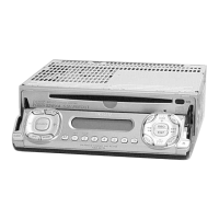
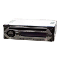
CDX-1150
Part s for Installation and Connections
The numbers in the list are keyed to those in the instructions.
FM/AM
Compact Disc
Player
5
1
× 2
2
6
7
3
8
4
Precautions
•Do not tamper with the four holes on the upper surface of the unit. They are for tuner adjustments to be
done only by service technicians.
•Choose the installation location carefully so that the unit will not hamper the driver during driving.
•Avoid installing the unit where it would be subject to high temperatures, such as from direct sunlight or
hot air from the heater, or where it would be subject to dust, dirt or excessive vibration.
•Use only the supplied mounting hardware for a safe and secure installation.
M ount ing exam ple
Installation in the dashboard
2
With the TOP marking up
Bend these claw s, if necessary.
1
4
3
Dashboard
Fire w all
5
To support the unit
M ount ing the unit in a Japanese car
You may not be able to install this unit in some makes of Japanese cars. In such a case, consult your Sony dealer.
TOYOTA NISSAN
to dashboard/center console
Bracket
to dashboard/center console
7 max. size
5 × 6 mm
7 max. size
5 × 6 mm
Note
To prevent malf unction, inst all only w it h t he supplied screw s 7.
× 4
1
3 max. size M 4 × 6 mm
2
4
Bracket
7 max. size
5 × 6 mm
7 max. size
5 × 6 mm
7 max. size 5 × 6 mm
6
6
7 max. size 5 × 6 mm
7
6
1
2
Caution
Cautionary notice for handling the bracket 1.
Handle the bracket carefully to avoid injuring your fingers.
T
O
P
TOP
182 mm
53 mm
T
O
P
Bracket
Existing parts supplied to your car
Bracket
Existing parts supplied to your car
*I-3-866-374-12*(1)
Ribs
9
M ount ing angle adjustment
Adjust the mounting angle to less than 60°.
1
10 mm (
13
/ 32 in./po.)
4 mm (
3
/ 16 in./po.)
90º
2
9
Insert the supplied tool 9 betw een the unit and the frame, and rotate 90° to
release the hidden mounting spring. Repeat on the opposite side and remove
the frame.
Insert a flathead screw driver betw een the bracket and mounting spring. Gently
pry the spring tow ard the unit w hile pulling the unit out a little. Repeat on the
opposite side and remove the unit.
Removing t he unit
TO
P
With the ribs on bottom
1
Note
To prevent malf unction, inst all
only wit h the supplied screw s 7.
Downloaded from: https://www.usersmanualguide.com/